Flush catheter with flow directing sheath

a technology of flow directing sheath and catheter, which is applied in the field of flush catheter, can solve the problems of hydrating the patient, unable to provide ideal solutions, and ineffective methods,

Inactive Publication Date: 2010-03-25
LIGHTLAB IMAGING
View PDF18 Cites 95 Cited by
  • Summary
  • Abstract
  • Description
  • Claims
  • Application Information

AI Technical Summary

Problems solved by technology

All three of these methods provide less than ideal solutions.
The guide flush method requires a large flow rate of saline that can over hydrate the patient.
This method is also very ineffective when side branches are present.
For example, when blood flow is from a proximal to a distal end of the imaging probe, the selective flush catheter method has the inherent limitation that blood from the area proximal to the flush point is entrained into the flush solution at a point where the flush solution exits the catheter.
Increasing the flow rate of flush solution tends to entrain more blood, making it difficult to dilute the blood enough to provide a clear imaging area.
In addition, it is difficult to configure this type of device for a minirail delivery system.
However, the approach of the '893 patent has several deficiencies which prevent its use in an OCT application and which make it difficult to produce.
For example, the deflector shield must be at a distal end of the catheter, making it difficult to use a minitail type of delivery system.
Further, the design does not strongly direct the flushing solution in an axial proximal direction.
As such, the bolus of flushing solution does not flow very far toward the proximal end of the catheter and will not provide the long volume desirable for surveying a length of the artery wall.
Furthermore, radially directed jets of fluid can damage the sensitive endothelial layer of the vessel and could even perforate the vessel.

Method used


Image

  • Flush catheter with flow directing sheath
  • Flush catheter with flow directing sheath
  • Flush catheter with flow directing sheath

Examples


Embodiment Construction

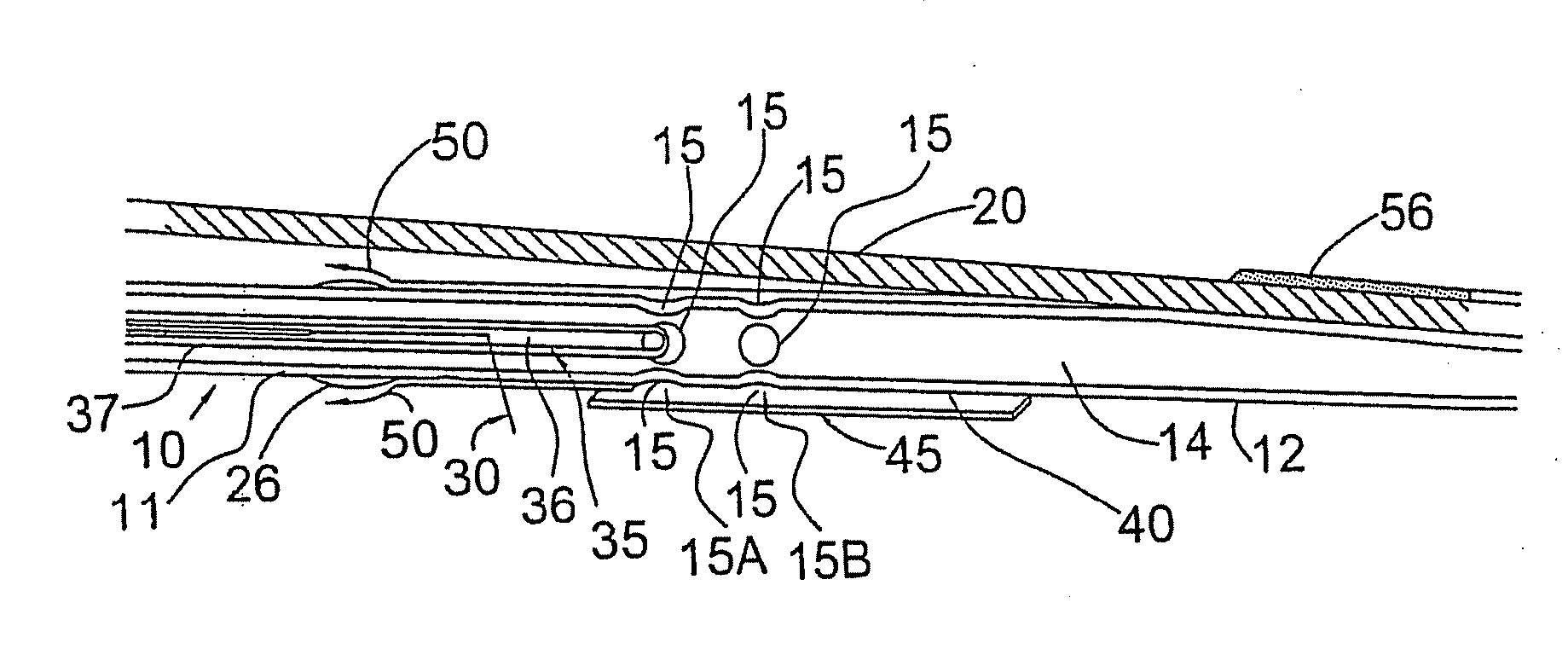
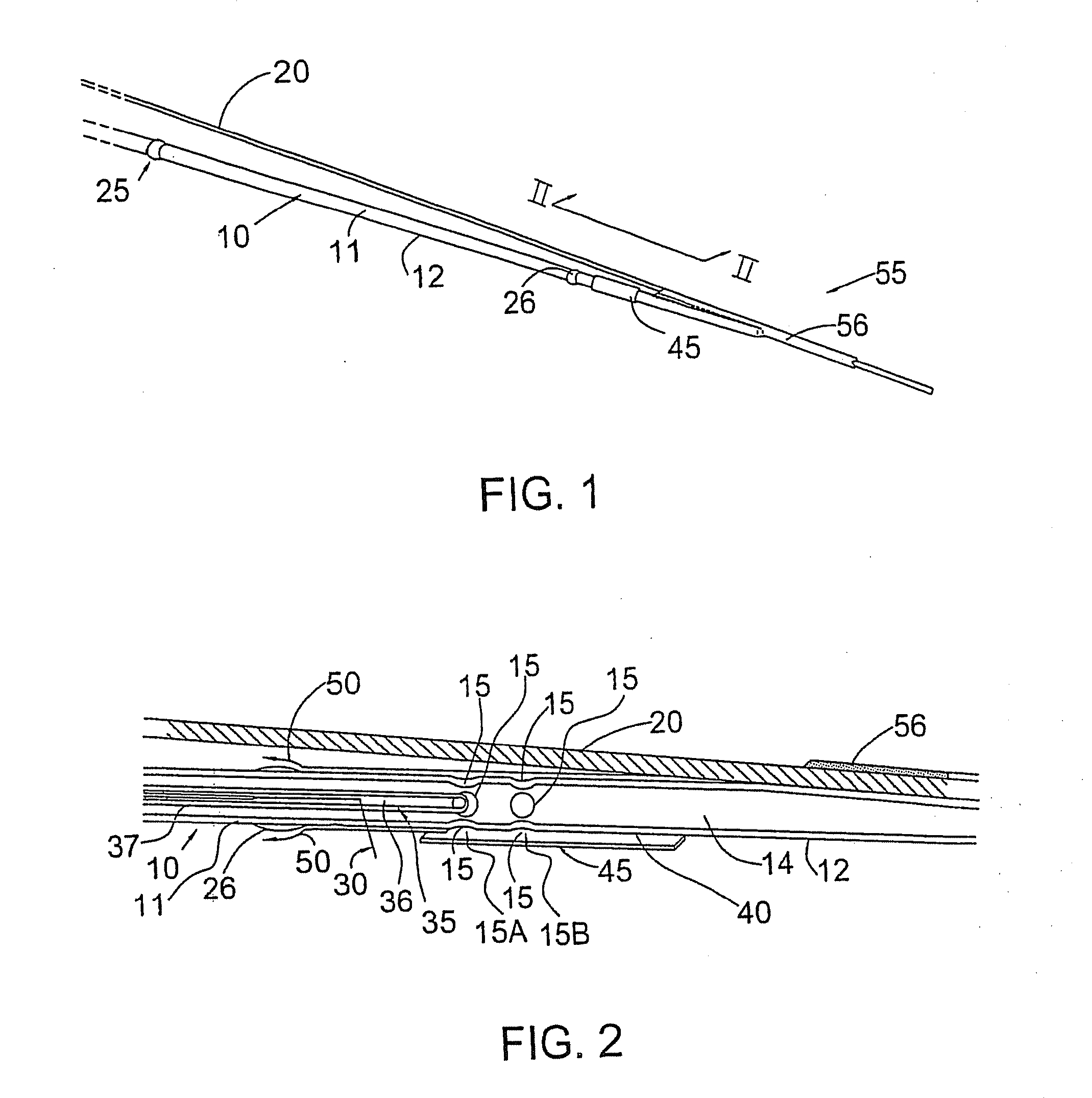
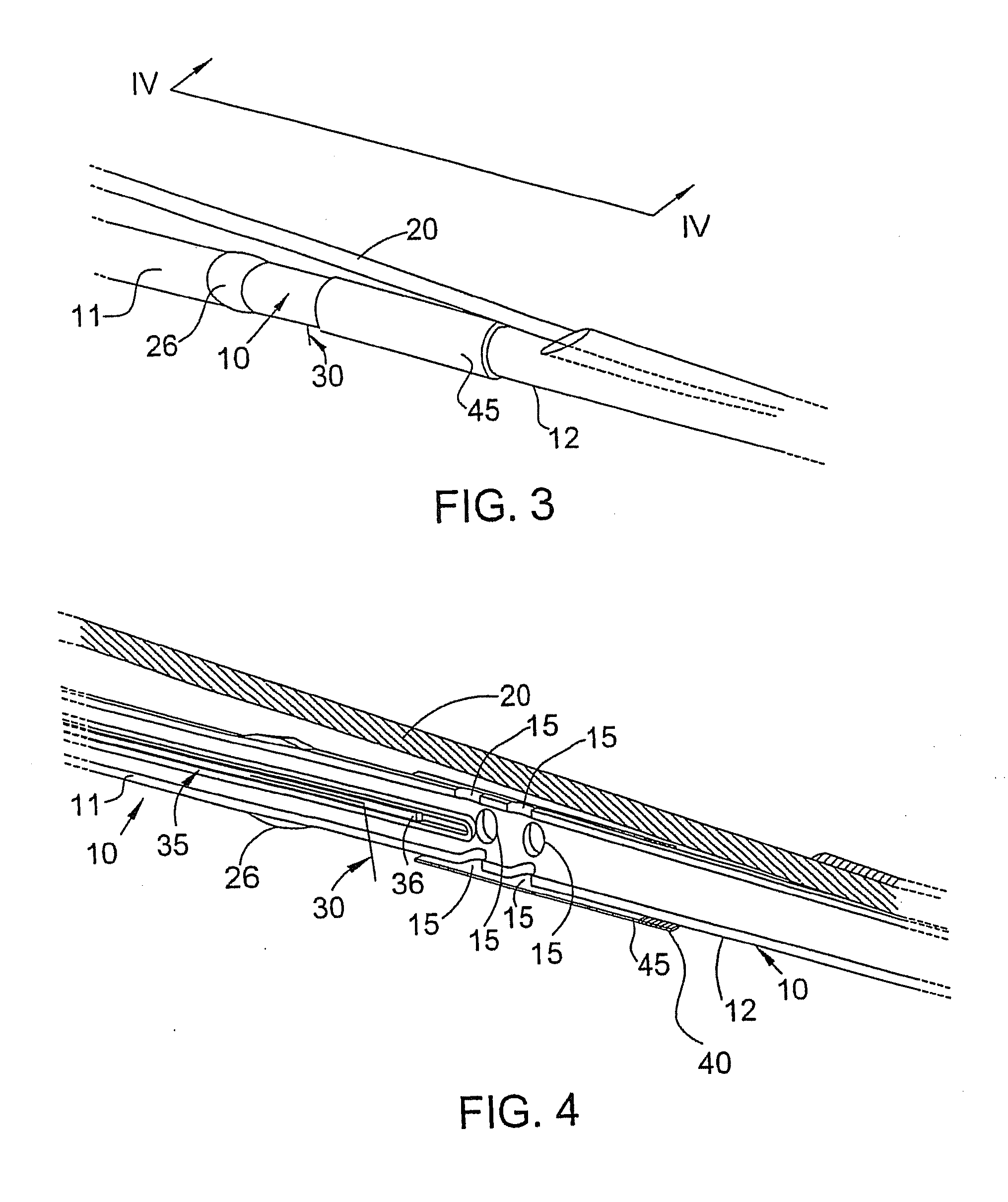
[0036]The invention is directed to a flush catheter configured to be inserted into an artery, vessel, or other orifice in a patient. In addition, embodiments of the invention are also directed to the use of flush solutions having predetermined viscosities.

[0037]Blood has a viscosity of approximately 3-4 centipoise (cps), dependant primarily on the hematocrit level. In contrast, water, by definition, has a viscosity of 1.00 cps. One of the primary contributors to flow resistance and hence blood pressure, is the resistance of the fine-diameter capillary bed at the terminus of each artery. When selecting among candidate flush solutions, the impact of this resistance on selected flow rate and pressure is an important consideration. If, for example, a saline flush were used, when collecting OCT imaging data, within one heart cycle the capillaries would fill with saline and the flow resistance would drop by a factor of 3 or more due to the viscosity change. To prevent blood from entering ...


PUM


Abstract

In certain embodiments, the invention provides a method of flushing a lumen of interest having a first diameter and a lumen wall. The method can include the steps of selecting a flush solution such that the flush solution lowers a fluid removal rate of a plurality of terminating lumens, the terminating lumens branching from and in fluid communication with the lumen of interest, at least one of the terminating lumens having a second diameter, the second diameter smaller than the first diameter; flushing the lumen with the flush solution; and collecting optical tomography scan data relative to a portion of the lumen wall.

Description

REFERENCE TO RELATED APPLICATIONS[0001]This application is a continuation-in-part of U.S. application Ser. No. 11 / 822,600, filed Jul. 9, 2007, which is a continuation of U.S. application Ser. No. 10 / 423,016, filed Apr. 25, 2003, now U.S. Pat. No. 7,241,286, the entire contents of each of which are hereby incorporated by reference herein.FIELD OF THE INVENTION[0002]The invention is directed to a flush catheter and, more particularly, to a flush catheter provided with a flow directing sheath.BACKGROUND OF THE INVENTION[0003]In order to obtain clear in-vivo images of arterial walls when using, for example, Optical Coherence Tomography (OCT), it is necessary to displace blood from a cylindrical volume around a tip of an imaging probe. To allow surveying of a length of an artery wall, it is desirable that the cylindrical volume be, for example, as long as approximately 40-50 mm or more. The better the blood is cleared from this volume, the better the image obtained of the arterial wall.[...

Claims


Application Information

Patent Timeline
Patent Type & Authority Applications(United States)
IPC IPC(8): A61M25/00A61B6/00
CPCA61B5/0066A61B5/0073A61B5/0084A61B5/02007A61M2025/0681A61M25/008A61M2025/0004A61M2025/0177A61M2025/0183A61M25/0069
Inventor PETERSEN, CHRISTOPHER L.ATLAS, MICHAELPETROFF, CHRISTOPHER
Owner LIGHTLAB IMAGING
Why Eureka
Try Eureka