
Air Flow Meter

Active Publication Date: 2010-04-01
HITACHI ASTEMO LTD
View PDF2 Cites 16 Cited by
  • Summary
  • Abstract
  • Description
  • Claims
  • Application Information

AI Technical Summary

Benefits of technology

[0007]In one of the structures where the peripheral part of the diaphragm section of the electrical insulating film is covered with the protective film made of an organic material, wires of the resistors on the diaphragm section cross the peripheral part of the diaphragm section. It has become clear that dust impact resistance is reduced at the place where narrow wires of the resistance temperature detectors and the like cross the peripheral part of the diaphragm section. It has been found that such reduction of dust impact resistance is caused because part of the protective film formed on the narrow wires is thinner than the other part and can absorb lower kinetic energy of dust.
[0008]On the other hand, at the place where the narrow wires of the resistance temperature detectors and the like cross the peripheral part of the diaphragm section, it has become clear that deflection occurs in the diaphragm section if the thickness of the protective film is made excessively thick in order to increase the dust kinetic energy that the protective film can absorb. It has been found that such deflection occurs because as the protective film gets thicker, tension due to the stress generated during formation of the protective film increases.
[0010]An object of the present invention is to provide a highly reliable thermal air flow meter in which the dust kinetic energy, that is, deformation energy that can be absorbed by a protective film provided for a measuring element is prevented from lowering
[0021]According to the present invention, it is possible to prevent the diaphragm from being broken by impact of dust particles to increase the reliability of the measuring element of the thermal air flow meter. This makes it possible to provide a highly reliable thermal air flow meter.

Problems solved by technology

It has been found that such deflection occurs because as the protective film gets thicker, tension due to the stress generated during formation of the protective film increases.
In the structure where the peripheral part of the diaphragm section of the electrical insulating film is covered with the protective film made of an organic material, it has been found that if the bodies of the resistance temperature detectors, that is, thermo-sensor sections are covered with the protective film, the characteristic of each resistance temperature detector is degraded, thus making it difficult to measure accurate flow rate.

Method used


Image

  • Air Flow Meter
  • Air Flow Meter
  • Air Flow Meter

Examples


first embodiment

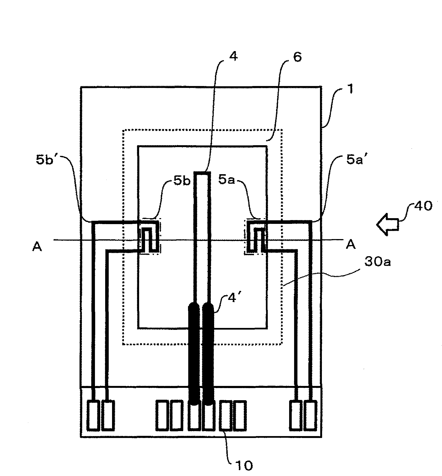
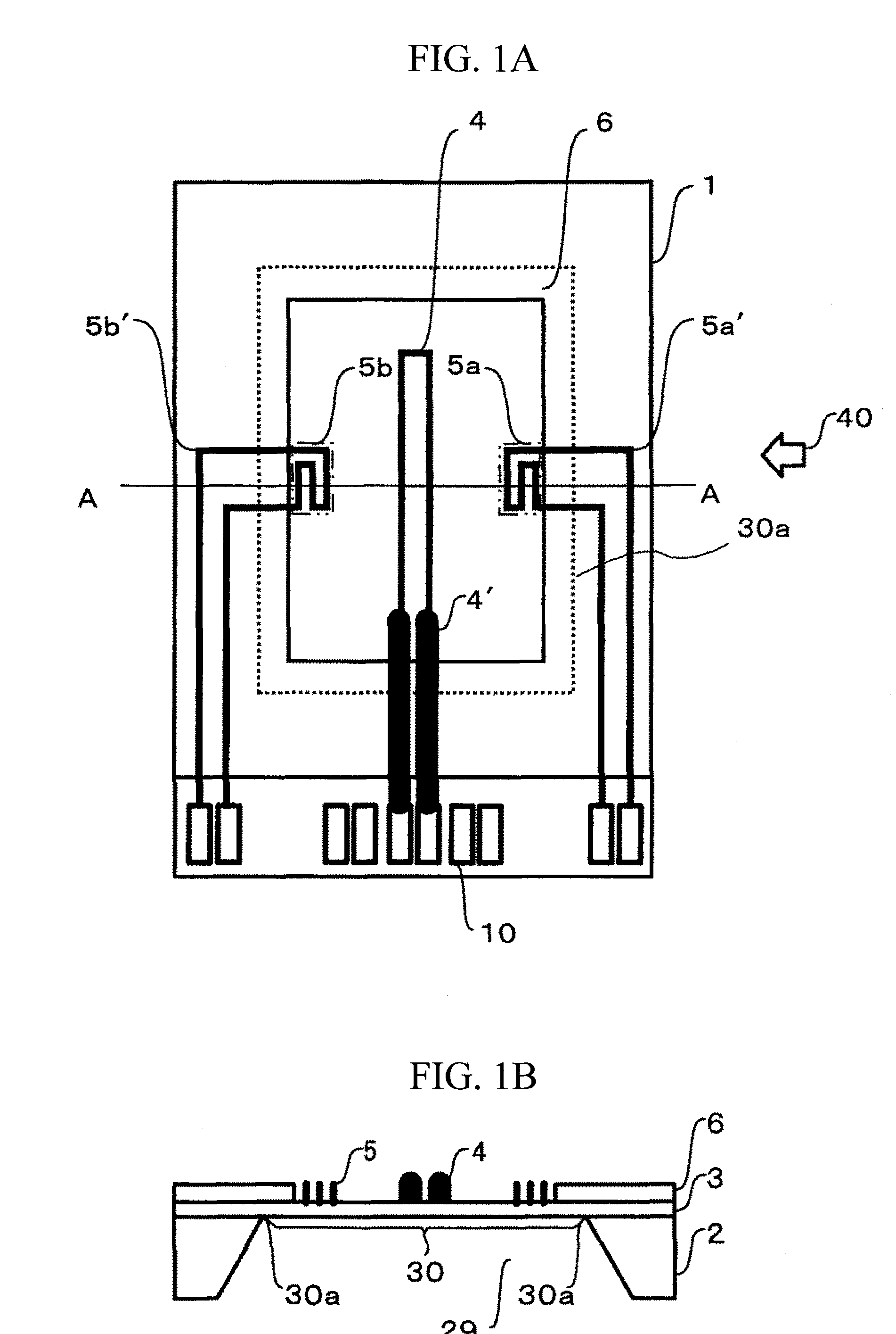
[0045]FIG. 1A is a schematic plan view of a measuring element of the thermal air flow meter, and FIG. 1 B is an enlarged cross-sectional view taken along a line A-A of FIG. 1A. As shown in FIG. 1A, a measuring element 1 provided for the thermal air flow meter of this embodiment includes: a semiconductor substrate 2; an electrical insulating film 3; a heating resistor body 4; a resistance temperature detector body 5 measuring temperature of the heating resistor body 4, and a protective film 6 protecting the electrical insulating film 3. The electrical insulating film 3 formed on the semiconductor substrate 2 composed of single-crystalline silicon or the like is a film having electrical and heat insulation, for example such as silicon dioxide (SiO2) film and a silicon dioxide film reinforced by a silicon nitride (Si3N4) film. On the electrical insulating film 3, the heating resistor body 4, resistance temperature detector body 5, and the like are formed, which are composed of semicond...

second embodiment

[0070]FIG. 16 shows another embodiment of the present invention. In this embodiment, instead of using the dummy wide wires 11, the heating resistor wires 4′ or resistance temperature detector wires 5a′ and 5b′ are partially widened to provide wide wires 8, thus obtaining a similar effect to the first embodiment. Generally, the width of the heating resistor wires 4′ is comparatively wide to reduce the resistance value. Accordingly, widening the temperature measuring resistance wires 5a′ and 5b′ is especially effective.

[0071]Since the thermal air flow meter measures the flow rate using changes in resistance value of the resistance temperature detector body 5, it is necessary to know an accurate resistance value. The wide wire 8 is sufficiently shorter than the entire length of the resistance temperature detector wires 5a′ and 5b′, so that the effect caused by the wide wire 8 can be neglected. Moreover, the widened part of each wire may be rectangular as shown in FIG. 16 or may be arra...


PUM


Abstract

In a structure in which peripheral part of a diaphragm section of an electrical insulating film is covered with a protective film made of an organic material, the resistor wire on the diaphragm section crosses the peripheral part of the diaphragm section. At a place where a narrow wire of a resistance temperature detector and the like crosses the peripheral part of the diaphragm section, the protective film is thinner than the other part, and the dust impact resistance is reduced. At a place where a heating resistor wire connected to a heating resistor body or resistance temperature detector wires connected to resistance temperature detector bodies cross a periphery of the diaphragm section, a film component protruding from an electrical insulating film is arranged side by side with the heating resistor wire or the resistance temperature detector wires.

Description

BACKGROUND OF THE INVENTION[0001]1. Field of the Invention[0002]The present invention relates to an air flow meter and more specifically, relates to a thermal air flow meter.[0003]2. Description of the Related Art[0004]As air flow meters, thermal air flow meters are becoming the mainstream because the thermal air flow meters can directly detect mass airflow. Especially thermal air flow meters including measuring elements manufactured by use of a semiconductor micromachining technique are attracting attention because of low cost and low-power drive thereof. Such thermal air flow meters are proposed in Japanese Patent Application Publication No. 10-311750 and the like. A measuring element of the thermal air flow meter proposed in Japanese Patent Application Publication No. 10-311750 includes: a semiconductor substrate; an electrical insulating film formed on the semiconductor substrate; and a plurality of resistors extending in parallel to each other on the electrical insulating film....

Claims


Application Information

Patent Timeline
IPC IPC(8): G01F1/692
CPCG01F1/6845
Inventor MINAMITANI, RINTAROHANZAWA, KEIJIYASUKAWA, AKIO
Owner HITACHI ASTEMO LTD
Learn More