Arrangement of components in a vehicle, and vehicle incorporating same

Inactive Publication Date: 2010-04-01
HONDA MOTOR CO LTD
View PDF9 Cites 29 Cited by
  • Summary
  • Abstract
  • Description
  • Claims
  • Application Information

AI Technical Summary

Benefits of technology

[0015]According to the first aspect of the present invention, the propeller shaft assembly for transmitting the driving force of the internal combustion engine includes the first propeller shaft disposed at the rear of the reduction gear and the second propeller shaft disposed at the front of the reduction gear. The reduction gear is located rearward of the pedal cluster and frontward of the occupant seats, and converts a rotational direction of the propeller shaft into a reverse direction. The second propeller shaft is offset toward the passenger seat in the vehicle width direction with respect to the first propeller shaft. This arrangement makes it possible to secure a large space for arrangement of pedal cluster, such as a brake pedal and an accelerator pedal, and thereby improve the flexibility in design.
[0016]According to the second aspect of the present invention, the fuel tank is disposed on the passenger seat side in such a manner as to overlap the first propeller shaft, when viewed in the side view. In other word, the fuel tank and the first propeller shaft are arranged side by side in the vehicle width direction. Accordingly, it possible to secure a large space for arrangement of the fuel tank with no limitation due to the propeller shaft, and to thus increase the tank capacity.
[0017]In addition, such arrangement of the fuel tank also makes it possible to reduce the thickness of a portion of the vehicle body below the occupant seats, thereby allowing the vehicle to have a low floor and a low center of gravity. Furthermore, since the fuel tank is located on the passenger seat (second seat) side, that is, a side opposite to the driver's seat (first seat) where a driver is always seated during operation of the vehicle, it is possible to improve the weight balance between the left and right sides of the vehicle body.
[0018]According to the third aspect of the present invention, the first propeller shaft is located substantially on the center line of the vehicle body. In addition, the second propeller shaft is offset toward the passenger seat (second seat) side substantially with respect to the center line of the vehicle body, and is connected to the final reducer on the passenger seat side in the vehicle width direction, and the final drive unit is disposed substantially on the center line of the vehicle body.
[0019]Accordingly, the first propeller shaft, the reduction gear, and the final drive unit can be substantially aligned with the center line of the vehicle body. Such arrangement of the first propeller shaft, the reduction gear, and the final drive unit makes it possible to achieve a favorable weight balance between the left and right sides of the vehicle, and also to secure a sufficient space for arrangement of the first seat and the second seat. Moreover, since the frame width can be suppressed to the minimum, the upper or lower frame can be elongated. In addition, since the swing angle can be made uniform between the left and right driveshafts, the wheel stroke can be further increased.

Problems solved by technology

However, in a vehicle having a lowered floor and a lowered center of gravity in pursuit of a sportier driving experience, such as a multi-use vehicle (MUV), the presence of a propeller shaft may limit the positions where the pedal cluster, e.g., a brake pedal and an accelerator pedal, may be placed.

Method used


Image

  • Arrangement of components in a vehicle, and vehicle incorporating same
  • Arrangement of components in a vehicle, and vehicle incorporating same
  • Arrangement of components in a vehicle, and vehicle incorporating same

Examples


Embodiment Construction

[0032]An embodiment of the present invention will now be described, with reference to the drawings. Throughout this description, relative terms like “upper”, “lower”, “above”, “below”, “front”, “back”, and the like are used in reference to a vantage point of an operator of the vehicle, seated on the driver's seat and facing forward. It should be understood that these terms are used for purposes of illustration, and are not intended to limit the invention.

[0033]Hereinafter, an illustrative embodiment according to a vehicle body and drive train structure of the present invention is described with reference a vehicle, particularly with reference to a multi-use vehicle (MUV). It may be noted that the drawings should be viewed in the direction of orientation of reference numerals.

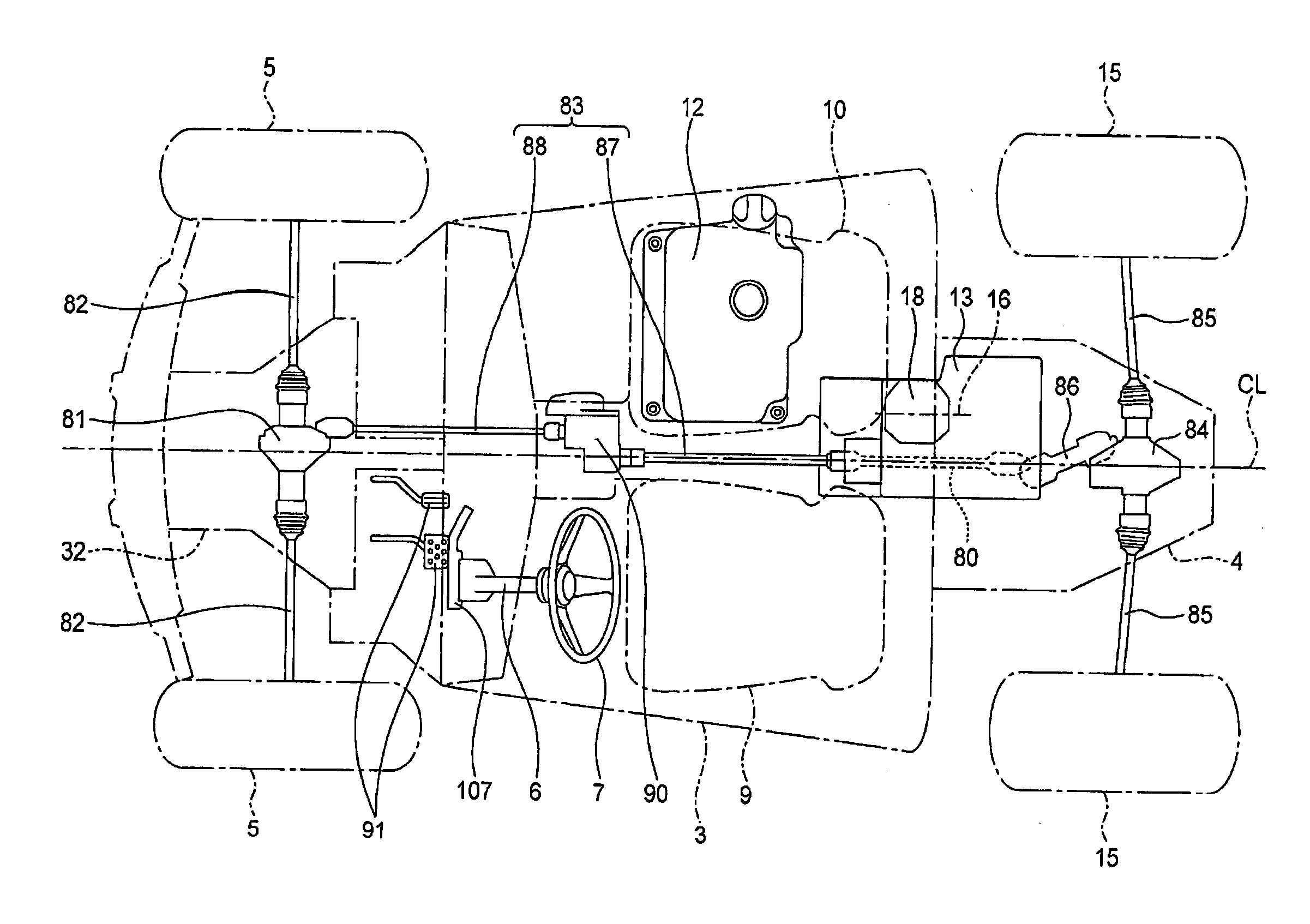
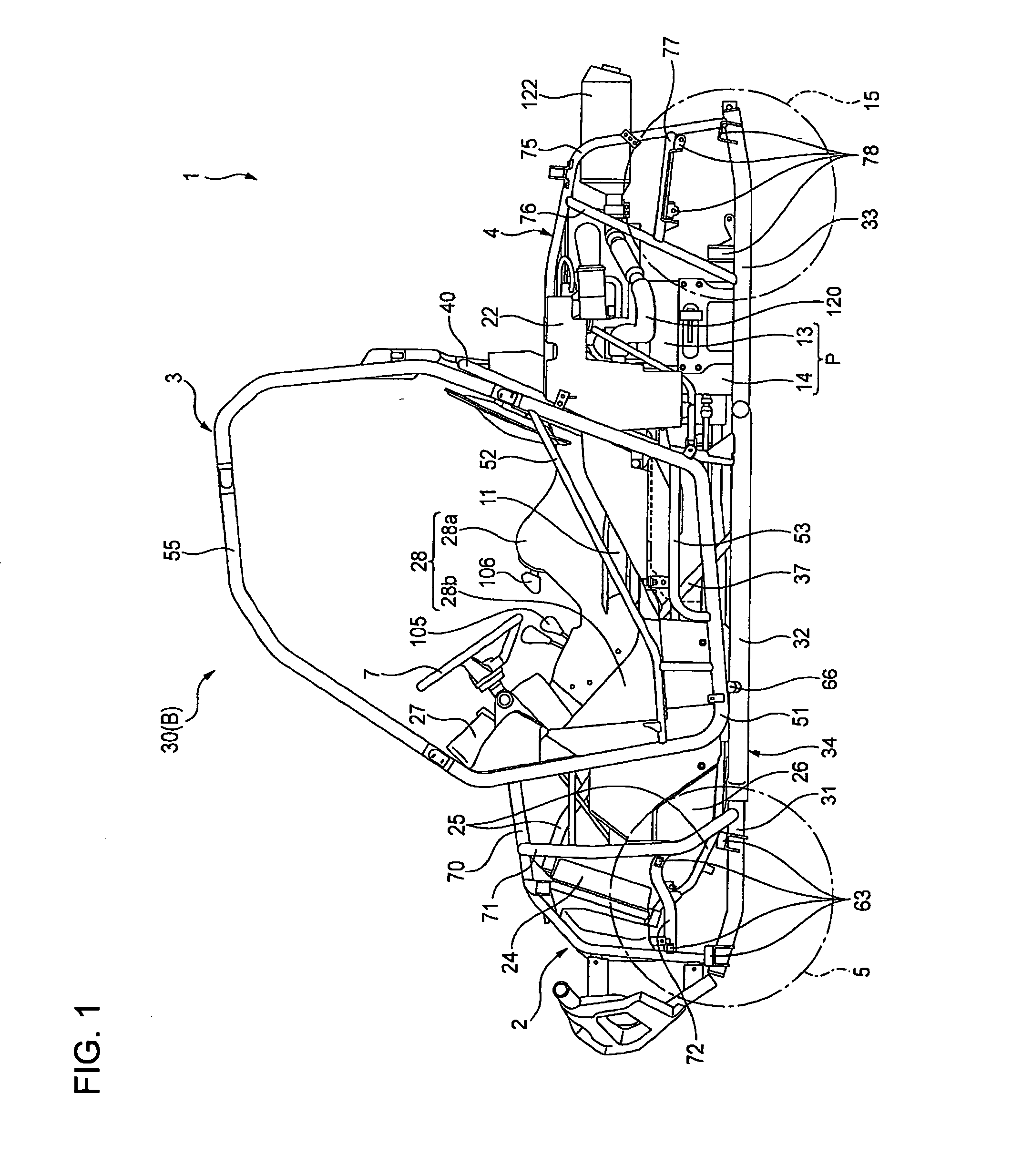
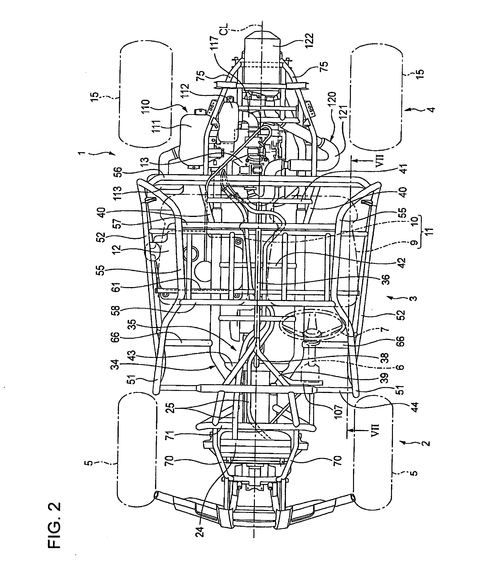
[0034]As shown in FIGS. 1 through 3, a vehicle 1 (for example, an MUV) according to the illustrative embodiment includes a vehicle body frame 30. The vehicle body frame 30 includes a front frame portion 2, a cen...


PUM


Abstract

A vehicle includes a vehicle body frame, an internal combustion engine supported on the vehicle body frame, a propeller shaft assembly operatively connected to a crankshaft of the engine, a driveshaft, a final drive unit disposed between the front propeller shaft assembly and the driveshaft, a pair of occupant seats arranged side by side in a vehicle width direction, a pedal cluster, and a reduction gear located rearward of the pedal cluster and frontward of the occupant seats. The propeller shaft assembly includes a first propeller shaft disposed at a rear of the reduction gear, and a second propeller shaft disposed at a front of the reduction gear. The second propeller shaft is offset toward a second seat side in a vehicle width direction with respect to the first propeller shaft.

Description

CROSS-REFERENCE TO RELATED APPLICATIONS[0001]The present invention claims priority under 35 USC 119 based on Japanese patent application No. 2008-253177, filed on Sep. 30, 2008. The entire subject matter of this priority document, including specification claims and drawings thereof, is incorporated by reference herein.BACKGROUND OF THE INVENTION[0002]1. Field of the Invention[0003]The present invention relates to an arrangement of selected drive train parts as well as other components in a vehicle, and to a vehicle incorporating the same. More particularly, the present invention relates to a vehicle drive train having a propeller shaft assembly, including a first propeller shaft disposed behind a reduction gear and a second propeller shaft disposed forward of the reduction gear, where the drive train components are arranged in relation to a vehicle frame as well as other vehicle components, and to a vehicle incorporating the described drive train and other components.[0004]2. Descri...

Claims


Application Information

Patent Timeline
IPC IPC(8): B60K17/00
CPCB60K5/02B60K13/02B60K17/34B60K17/04B60K17/22B60K13/04
Inventor KUWABARA, NAOKITOMITA, HIROAKI
Owner HONDA MOTOR CO LTD
Why Eureka
Try Eureka