Electric power converter

a technology of electric power converters and converters, which is applied in the direction of motor/generator/converter stoppers, dynamo-electric converter control, instruments, etc., can solve the problems of temporary over-current or failure or malfunction of a constituent element, and over-current and over-voltage in the circuit, etc., to achieve reliable protective operation and reliable protection operation

a technology of electric power converters and converters, which is applied in the direction of motor/generator/converter stoppers, dynamo-electric converter control, instruments, etc., can solve the problems of temporary over-current or failure or malfunction of a constituent element, and over-current and over-voltage in the circuit, etc., to achieve reliable protective operation and reliable protection operation

US20100079093A1Inactive Publication Date: 2010-04-01MITSUBISHI ELECTRIC CORP

Image

  • Electric power converter
  • Electric power converter
  • Electric power converter

Examples


embodiment 1

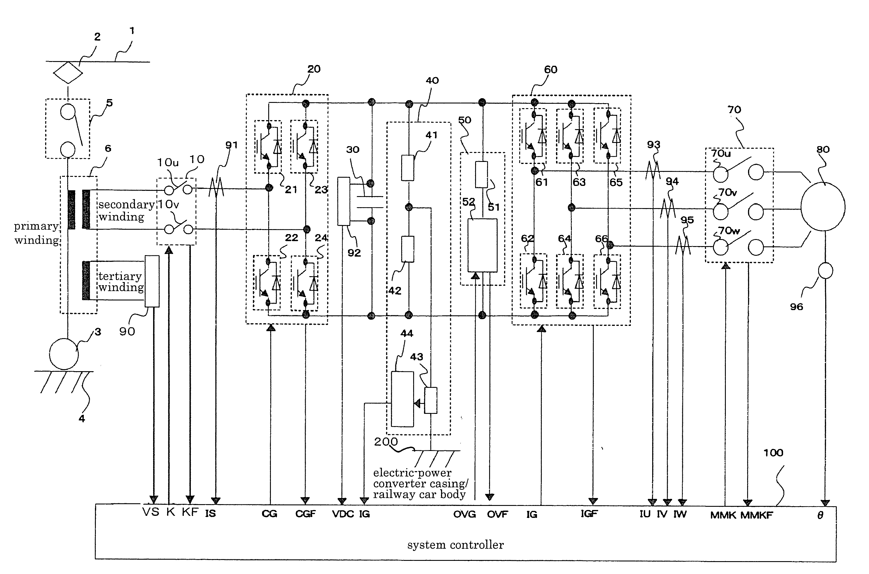
[0052]FIG. 1 is a diagram illustrating a configuration example of an electric power converter applied to a controller of an electric railway car, according to Embodiment 1 of the present invention. As shown in FIG. 1, electric power is supplied into the main circuit of the power converter from an overhead wire 1 (its AC voltage is generally 20 kV-25 kV) through a current collector 2, and fed to the primary side of a transformer 6 through a breaker 5. The other end of the transformer 6 is connected to rails 4 at the ground potential through wheels 3. It is noted that the breaker 5 has a capability of interrupting a fault current generated when a short circuit occurs; on the other hand, a supply-side contactor 10 and a motor-side contactor 70, which will be explained later, have no capability of interrupting such a fault current.

[0053]The transformer 6 steps down the voltage input into its primary winding, to output from its secondary and tertiary windings the respective stepped down ...


PUM


Abstract

Specific anomalies and details of failures as well as measures thereagainst are described that might possibly occur in electric power converters that drive and control permanent-magnet synchronous motors. An electric power converter capable of stable operation has a protective function of taking proper measures against such failures that might possibly occur.

Description

TECHNICAL FIELD[0001]The present invention relates to electric power converters that drive and control permanent-magnet synchronous motors.BACKGROUND ART[0002]Permanent-magnet synchronous motors (hereinafter simply referred to as “motors”) are known as high-efficiency motors in comparison with most-used conventional induction motors, because magnetic field is established by the permanent magnet which results in no need for excitation current and no current flows through the rotor which results in no secondary copper loss. While induction motors are conventionally used in electric railway cars, application of permanent-magnet synchronous motors to electric railway cars has been investigated in recent years to enhance efficiency thereof.[0003]In electric power converters used in controllers of electric railway cars that drive and control the permanent-magnet synchronous motors, a stable operation is required in which the possibility of a halt in operation due to failure or of a breaka...

Claims


Application Information

Patent Timeline
01 Apr 2010
Publication
US20100079093A1
IPC
H02P27/00
CPC
B60L3/003; B60L3/0069; B60L3/04; B60L9/28; B60L2200/26; Y02T10/646; Y10S388/903; Y02T10/648
Inventors
KITANAKA, HIDETOSHI