Device and a method for polarized illumination of a micro-display

Active Publication Date: 2010-04-01
NOKIA TECHNOLOGLES OY
View PDF3 Cites 82 Cited by
  • Summary
  • Abstract
  • Description
  • Claims
  • Application Information

AI Technical Summary

Benefits of technology

[0029]The use of the light distributing device according to the invention may allow reduction of the distance between a display element and imaging optics. This may allow a reduced back focal length and/or increased freedom to choose the parameters of the optics.
[0030]The light distributing device may distribute light provided by a ligh

Problems solved by technology

Thus, it may be difficult to incorporate a prior

Method used


Image

  • Device and a method for polarized illumination of a micro-display
  • Device and a method for polarized illumination of a micro-display
  • Device and a method for polarized illumination of a micro-display

Examples


example 1

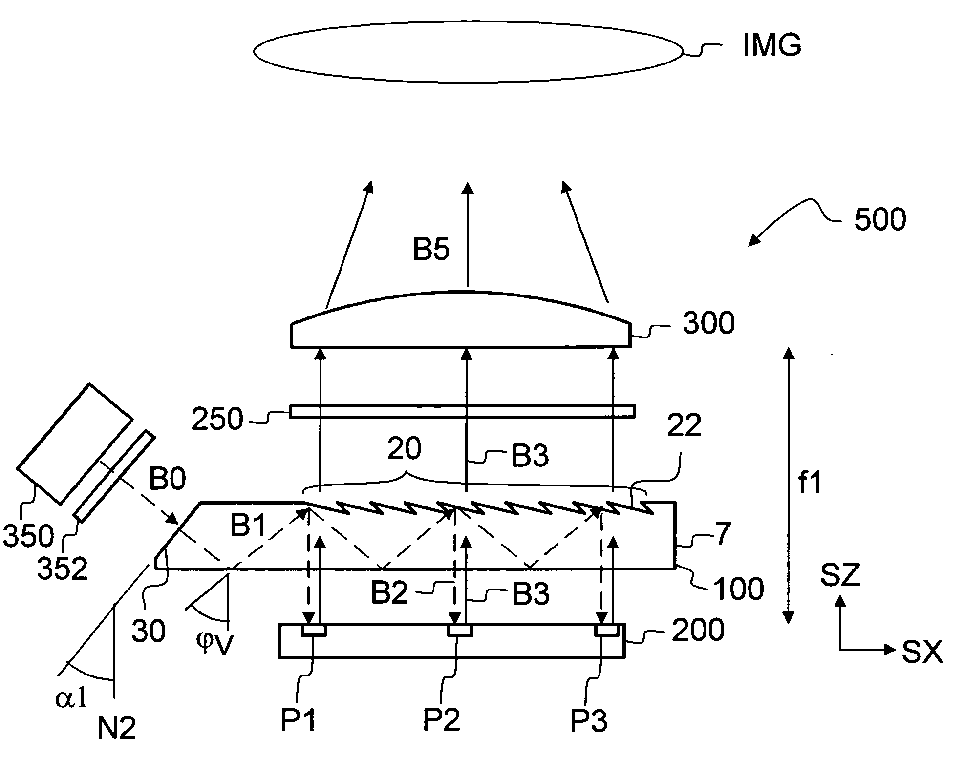
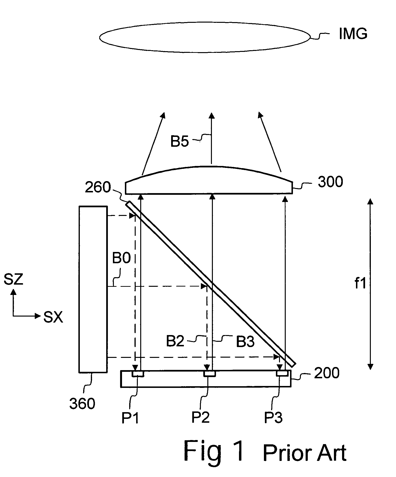
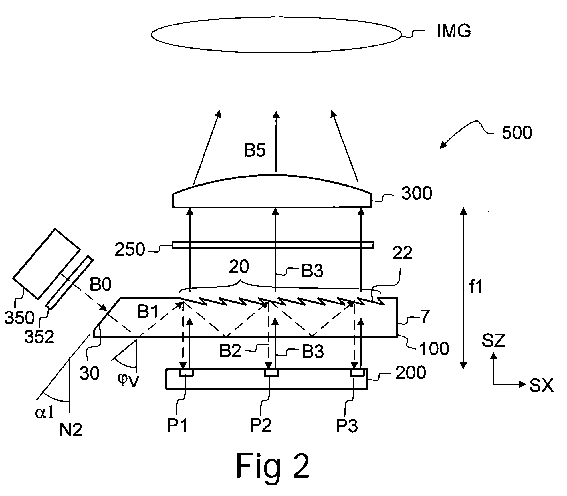
[0175]A device (500) comprising:[0176]a light source (350) to provide an input light beam (B0),[0177]a substrate (7) having an input surface (30) to form an in-coupled light beam (B1) by receiving light of said input light beam (B0), wherein said in-coupled light beam (B1) is substantially polarized, and wherein said in-coupled light beam B1 is confined to said substrate (7) by total internal reflections, and said substrate (7) further comprising a plurality of out-coupling features (22) to form an illuminating light beam (B2) by diffracting light of said in-coupled light beam (B1) out of said substrate (7),[0178]a display element (200) having a plurality of reflective polarization-rotating pixels (P1, P2, P3) arranged to form reflected light beams (B3) by reflecting light of said illuminating light beam (B2), and[0179]imaging optics (300) to form an image (IMG) by focusing or collimating light of said reflected light beams (B3) transmitted through said out-coupling features (22).

example 2

[0180]The device (500) of example 1 wherein said out-coupling features (22) are arranged to transmit light of said reflected light beams (B3) towards said imaging optics (300) when the light of said reflected light beams (B3) has a first polarization state and to at least partially prevent transmission of light of said reflected light beams (B3) towards said imaging optics (300) when the light of said reflected light beams (B3) has a second polarization state.

example 3

[0181]The device (500) of example 1 or 2 wherein said out-coupling features (22) form a diffractive grating having an overhanging sawtooth profile.


PUM


Abstract

A display device comprises a light source to provide an input light beam, a substrate having an input surface to form an in-coupled light beam by receiving light of the input light beam, wherein the in-coupled light beam is confined to the substrate by total internal reflections, the substrate further comprising a plurality of out-coupling features to form an illuminating light beam by diffracting light of the in-coupled light beam out of the substrate, a display element having a plurality of reflective polarization-rotating pixels arranged to form reflected light beams by reflecting light of the illuminating light beam, and imaging optics to form an image by focusing or collimating light of the reflected light beams transmitted through the out-coupling features.

Description

FIELD OF THE INVENTION[0001]The present invention relates to display devices (apparatuses) comprising polarization-rotating reflective display elements.BACKGROUND OF THE INVENTION[0002]Referring to FIG. 1, an image projector according to prior art comprises a light source 360 to provide light B0, and a polarizing beam splitter 260 to form a polarized illuminating light B2 by reflecting light B0. The illuminating light B2 impinges on the pixels P1, P2, P3 of a reflective micro display 200. Depending on the state of the pixels P1, P2, P3, light B3 reflected from each pixel P1, P2, P3 may have the same polarization state as the illuminating light B2, or its polarization may be changed. Only light whose polarization state has been changed passes through the splitter 260 to the imaging optics 300. The imaging optics 300 focuses or collimates light B3 so as to form light B5. The light B5 may be directed to a screen in order to project an image IMG.[0003]The polarizing beam splitter 260 is...

Claims


Application Information

Patent Timeline
IPC IPC(8): G02B6/024G02F1/01F21V8/00
CPCG02B6/002G02B6/0056G02B6/0038
Inventor LEVOLA, TAPANI
Owner NOKIA TECHNOLOGLES OY
Why Eureka
Try Eureka