Spin current generator for stt-mram or other spintronics applications

a current generator and spintronics technology, applied in the direction of generators/motors, magnetic bodies, instruments, etc., can solve the problems of less efficient and complicated bidirectional programming logic, less efficient than the conventional electronic method of controlling electron charge by applying voltage, and more cell space for bidirectional programming logi

Active Publication Date: 2010-04-01
OVONYX MEMORY TECH LLC
View PDF35 Cites 20 Cited by
  • Summary
  • Abstract
  • Description
  • Claims
  • Application Information

AI Technical Summary

Problems solved by technology

However, the conventional electronic methods of operation by applying voltage to control electron charge are fundamentally limited.
However, bidirectional programming logic requires more cell space.
Furthermore, bidirectional programming logic is generally more complicated and less efficient than unidirectional programming logic.

Method used


Image

  • Spin current generator for stt-mram or other spintronics applications
  • Spin current generator for stt-mram or other spintronics applications
  • Spin current generator for stt-mram or other spintronics applications

Examples


Embodiment Construction

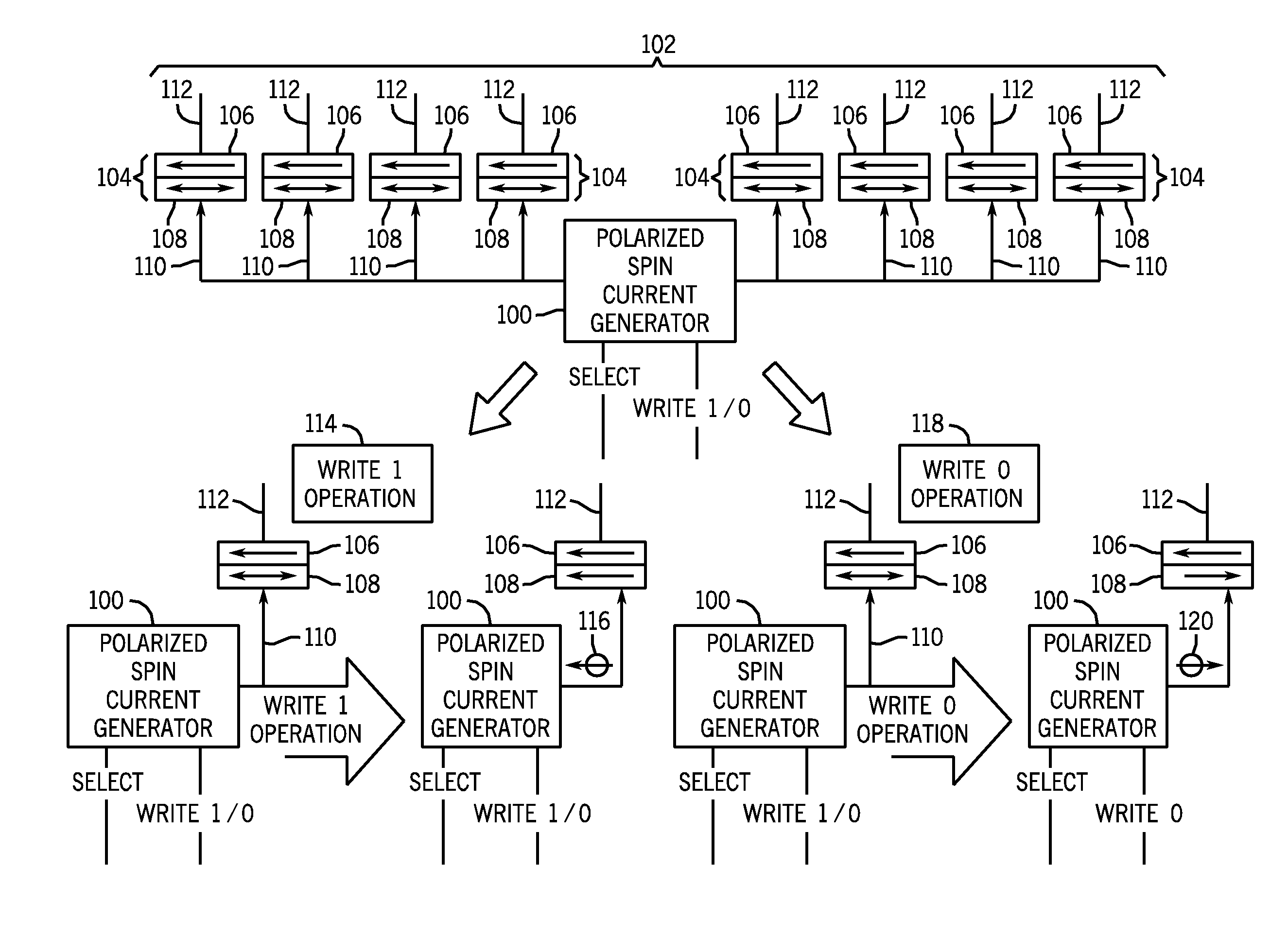
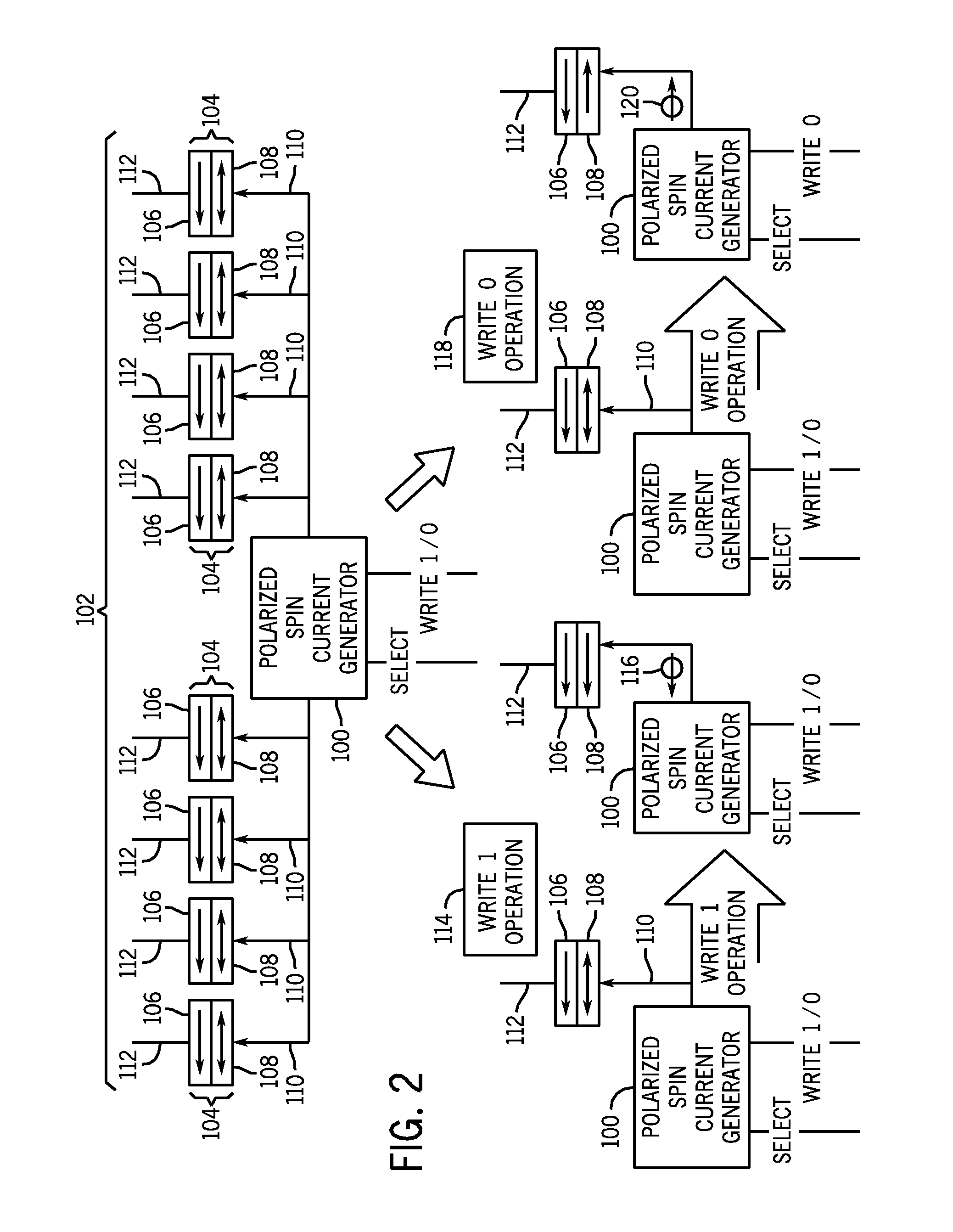
[0013]Spintronics devices write and store information by manipulating electron spin in a particular orientation. As previously discussed, information may be stored by programming magnetic layers in a memory cell into low resistance and high resistance states. Switching between the two resistance states typically employs a bidirectional programming current, where a current passed in one direction may orient the magnetization of memory cell layers to a low resistance state, and a current passed in an opposite direction may orient the magnetization of memory cell layers to a high resistance state. Since bidirectional programming logic requires more complicated circuitry and more chip space, a method of generating electron currents with desired spin polarizations may reduce the complexity and size of memory cell area or other devices requiring currents of different polarities by facilitating unidirectional programming. The following discussion describes the systems and devices, and the ...


PUM


Abstract

Spin current generators and systems and methods for employing spin current generators. A spin current generator may be configured to generate a spin current polarized in one direction, or a spin current selectively polarized in two directions. The spin current generator may by employed in spintronics applications, wherein a spin current is desired.

Description

BACKGROUND[0001]1. Field of Invention[0002]The invention relates generally to current generators, and more particularly, to spin current generators for spintronics applications.[0003]2. Description of Related Art[0004]This section is intended to introduce the reader to various aspects of the art that may be related to various aspects of the present invention, which are described and / or claimed below. This discussion is believed to be helpful in providing the reader with background information to facilitate a better understanding of the various aspects of the present invention. Accordingly, it should be understood that these statements are to be read in this light and not as admissions of prior art.[0005]The development of microelectronics has led to large increases in integration density and efficiency. However, the conventional electronic methods of operation by applying voltage to control electron charge are fundamentally limited. Further improvements in nonvolatility, speed, and ...

Claims


Application Information

Patent Timeline
Patent Type & Authority Applications(United States)
IPC IPC(8): H01L41/00G11C11/00
CPCB82Y25/00G01R33/093G01R33/1284Y10S977/934H01F10/3218B82Y10/00G11C11/1675G11C11/16
Inventor LIU, JUNSANDHU, GURTEJ
Owner OVONYX MEMORY TECH LLC
Why Eureka
Try Eureka