Spin current magnetization rotational element, magnetoresistance effect element, and magnetic memory

Active Publication Date: 2018-06-07
TDK CORPARATION
View PDF1 Cites 16 Cited by
  • Summary
  • Abstract
  • Description
  • Claims
  • Application Information

AI Technical Summary

Benefits of technology

[0026]According to the spin current magnetization rotational element of the present invention, it is possible to provide a spin

Problems solved by technology

The problems of SOT are structural limitations and material limitations.
Since SOT utilizes the torque generated at the interface between the ferromagnetic metal la

Method used


Image

  • Spin current magnetization rotational element, magnetoresistance effect element, and magnetic memory
  • Spin current magnetization rotational element, magnetoresistance effect element, and magnetic memory
  • Spin current magnetization rotational element, magnetoresistance effect element, and magnetic memory

Examples


Embodiment Construction

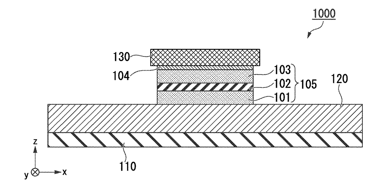
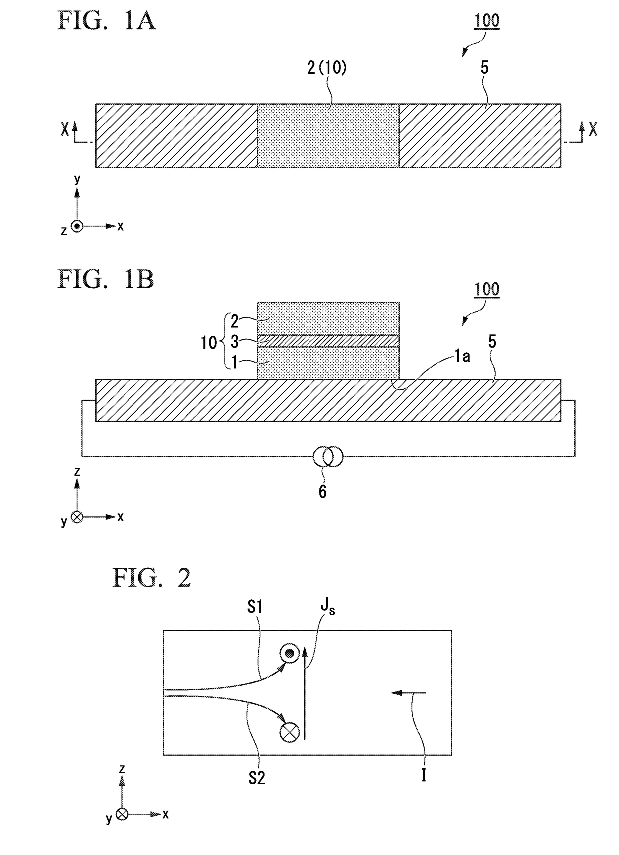
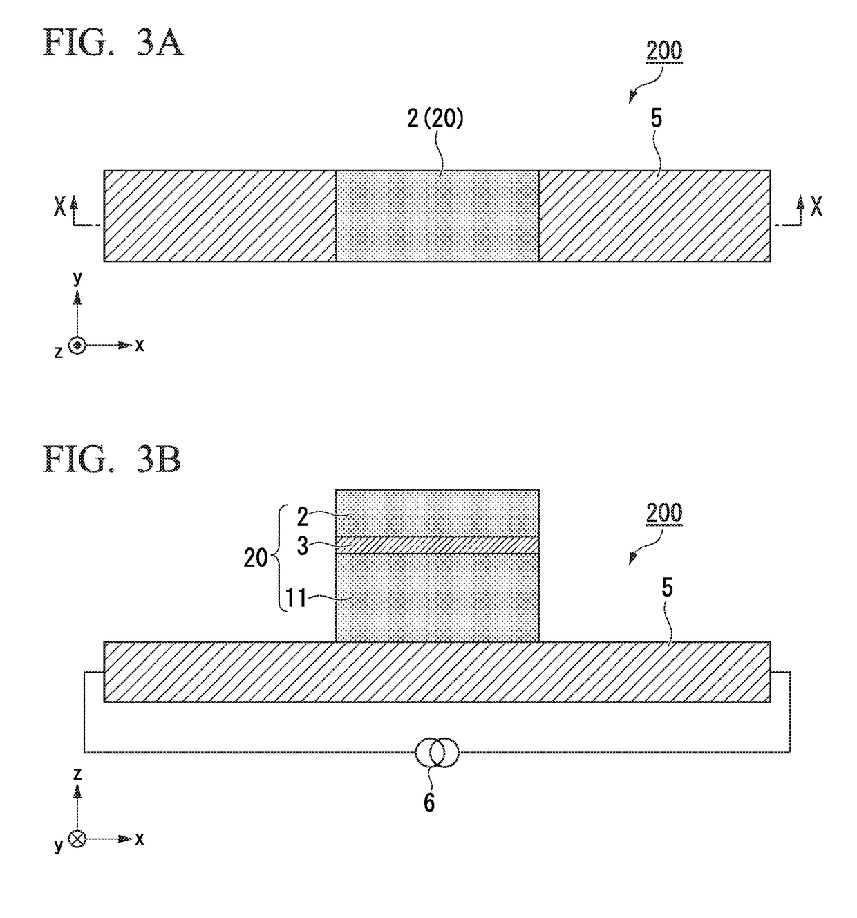
[0036]Hereinafter, the present invention will be described in detail with reference to the drawings. In the drawings used in the following description, for the sake of clarity of the features of the present invention, there are cases where characteristic portions are enlarged for the sake of convenience, and the dimensional ratios of the respective components are different from actual ones. The materials, dimensions, and the like exemplified in the following description are merely examples, and the present invention is not limited thereto, and can be carried out by appropriately changing within a range that exerts the effects of the present invention. In the element of the present invention, other layers may be provided as long as the effect of the present invention is achieved.

[0037]FIGS. 1A and 1B show schematic diagrams of an example of a spin current magnetization rotational element according to one embodiment of the present invention. FIG. 1A is a plan view and FIG. 1B is a cro...


PUM


Abstract

A spin current magnetization rotational element includes: a magnetization free layer including a synthetic structure consisting of a first ferromagnetic metal layer, a second ferromagnetic metal layer and a first non-magnetic layer sandwiched by the first ferromagnetic metal layer and the second ferromagnetic metal layer; and an antiferromagnetic spin-orbit torque wiring that extends in a second direction intersecting with a first direction that is a lamination direction of the synthetic structure and is joined to the first ferromagnetic metal layer, wherein the spin current magnetization rotational element is configured to change a magnetization direction of the magnetization free layer by applying current to the antiferromagnetic spin-orbit torque wiring.

Description

BACKGROUND OF THE INVENTIONTechnical Field[0001]The present invention relates to a spin current magnetization rotational element, a magnetoresistance effect element, and a magnetic memory.[0002]Priority is claimed on Japanese Patent Application No. 2016-235236, filed Dec. 2, 2016, the content of which is incorporated herein by reference.Description of Related Art[0003]A giant magnetoresistance (GMR) element composed of a multilayer film of a ferromagnetic metal layer and a non-magnetic layer and a tunneling magnetoresistance (TMR) element using an insulating layer (a tunnel barrier layer, a barrier layer) as a non-magnetic layer are known. In general, although the TMR element has higher element resistance than the GMR element, the magnetoresistance (MR) ratio is larger than the MR ratio of the GMR element. Therefore, TMR elements are of interest as elements for magnetic sensors, high frequency components, magnetic heads and nonvolatile random access memories (MRAM).[0004]The MRAM re...

Claims


Application Information

Patent Timeline
IPC IPC(8): H01L43/08H01L43/02G11C11/16H01L43/10H01L27/22
CPCH01L43/08H01L43/02G11C11/161H01L43/10H01L27/222H10N50/80H10N50/85H10N50/10H10B61/00H01L27/1222
Inventor SHIOKAWA, YOHEISASAKI, TOMOYUKISHIBATA, TATSUO
Owner TDK CORPARATION
Why Eureka
Try Eureka