

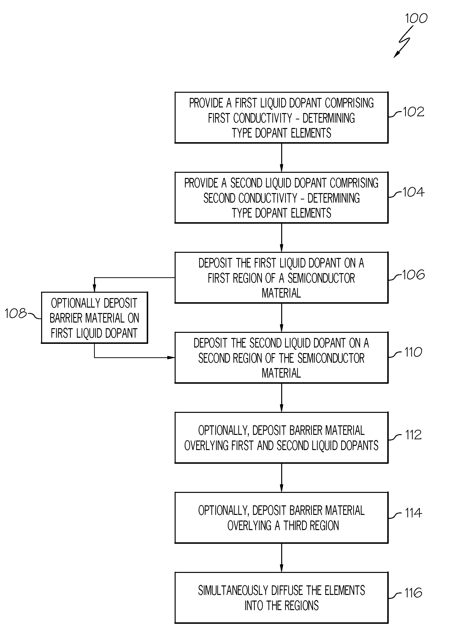
Methods for simultaneously forming n-type and p-type doped regions using non-contact printing processes
a technology of non-contact printing and semiconductor materials, which is applied in the field of semiconductor device fabrication, can solve the problems of prohibitively difficult, if not impossible, to obtain very fine and/or narrow doped regions in semiconductor substrates using screen printing, and the cost and time-consuming process of using photolithography to form different doped regions
- Summary
- Abstract
- Description
- Claims
- Application Information
AI Technical Summary
Problems solved by technology
Method used
Image

Examples
example
[0042]Synthesis of Printable Boron Ink: About 1100 grams (gm) B30 borosilicate, available from Honeywell International of Morristown, N.J., was mixed with 110 gm acetoxytrimethylsilane and left at room temperature for about three hours to form an end-capped boron silicate ink. The end-capped boron silicate ink then was concentrated by distilling off about 908 gm solvent in a rotary evaporator while keeping the solution at a temperature below 23° C. The final weight of the end-capped boron silicate ink was 302 gm. 302 gm ethanol was added to 302 gm of the end-capped boron silicate. A final end-capped boron silicate ink was prepared by adding 10.0 gm boric acid to the 604 gm solution, stirring to dissolve the boric acid, and then filtering using a 0.2 micron (μm) nylon filter. The composition of the final end-capped boron silicate ink was 49.2 weight percent (wt. %) end-capped boron silicate ink, 49.2 wt. % ethanol, and 1.6 wt. % boric acid. The viscosity was about 3.5 centipoise (cp)...
PUM
 Abstract
Description
Claims
Application Information