Composite Screw Having A Metallic Pin and a Polymeric Thread

a technology of composite screw and polymer thread, which is applied in the field of composite screw having, can solve the problems of screw loosening and failure of the construction, and achieve the effects of reducing the thickness increasing the adhesion of the polymeric tube, and variable stiffness

Inactive Publication Date: 2010-04-01
DEPUY SYNTHES PROD INC
View PDF25 Cites 28 Cited by
  • Summary
  • Abstract
  • Description
  • Claims
  • Application Information

AI Technical Summary

Benefits of technology

[0016]The metallic shaft can be textured for increased adhesion of polymeric tube thereto. The polymer can be selected from any biocompatible polymer (and is preferably PEEK) and may be reinforced by fibers. The metallic shaft can be made of any biocompatible metal, and preferably comprises titanium.
[0017]In preferred embodiments, the composite screw has a variable stiffness along the screw shaft from the tip to the head. This is typically accomplished by reducing its thickness. Preferably, the composite screw is more flexible than the typical metal screw, yet possesses a conventional metallic head. Typically, the composite screw has three principal sections possessing different stiffnesses: a) a distal section composed primarily of polymer and having stiffness similar to that of cancellous bone, b) a middle section composed of both polymer and metal with an overall stiffness similar to that of cortical bone, and c) a proximal metallic section having the neck and the head of the screw. The composite screw will preferably reduce or eliminate the screw toggling and therefore screw loosening. This is viewed as having particular advantage for osteoporotic bones. The composite screw is meant to reduce the stiffness of the screw by introducing polymeric thread.

Problems solved by technology

This mismatch in stiffness may cause fracture in the surrounding cancellous vertebra body bone, allowing the screw to undesirably toggle (like a windshield wiper) within the vertebra body.
This toggling ultimately leads to screw loosening and failure of the construct.

Method used


Image

  • Composite Screw Having A Metallic Pin and a Polymeric Thread
  • Composite Screw Having A Metallic Pin and a Polymeric Thread

Examples


Embodiment Construction

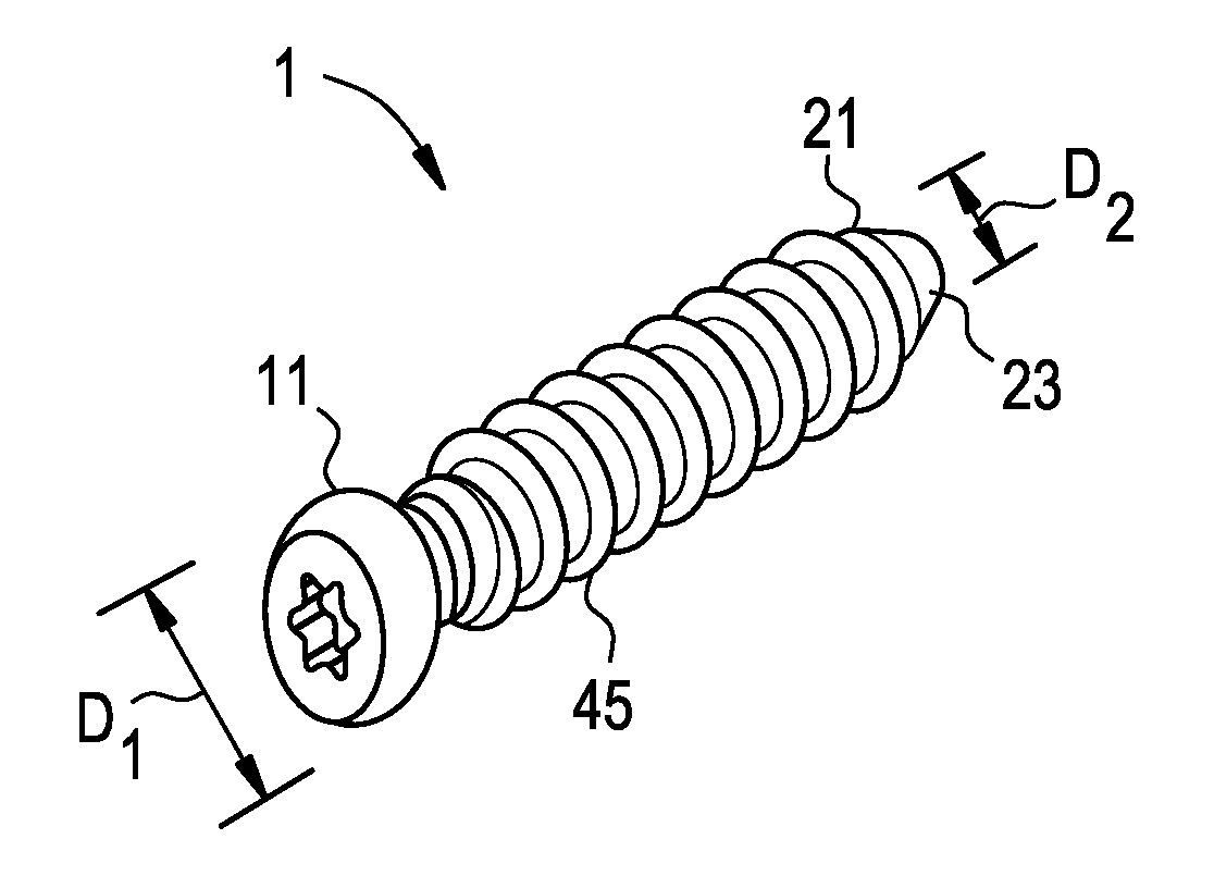
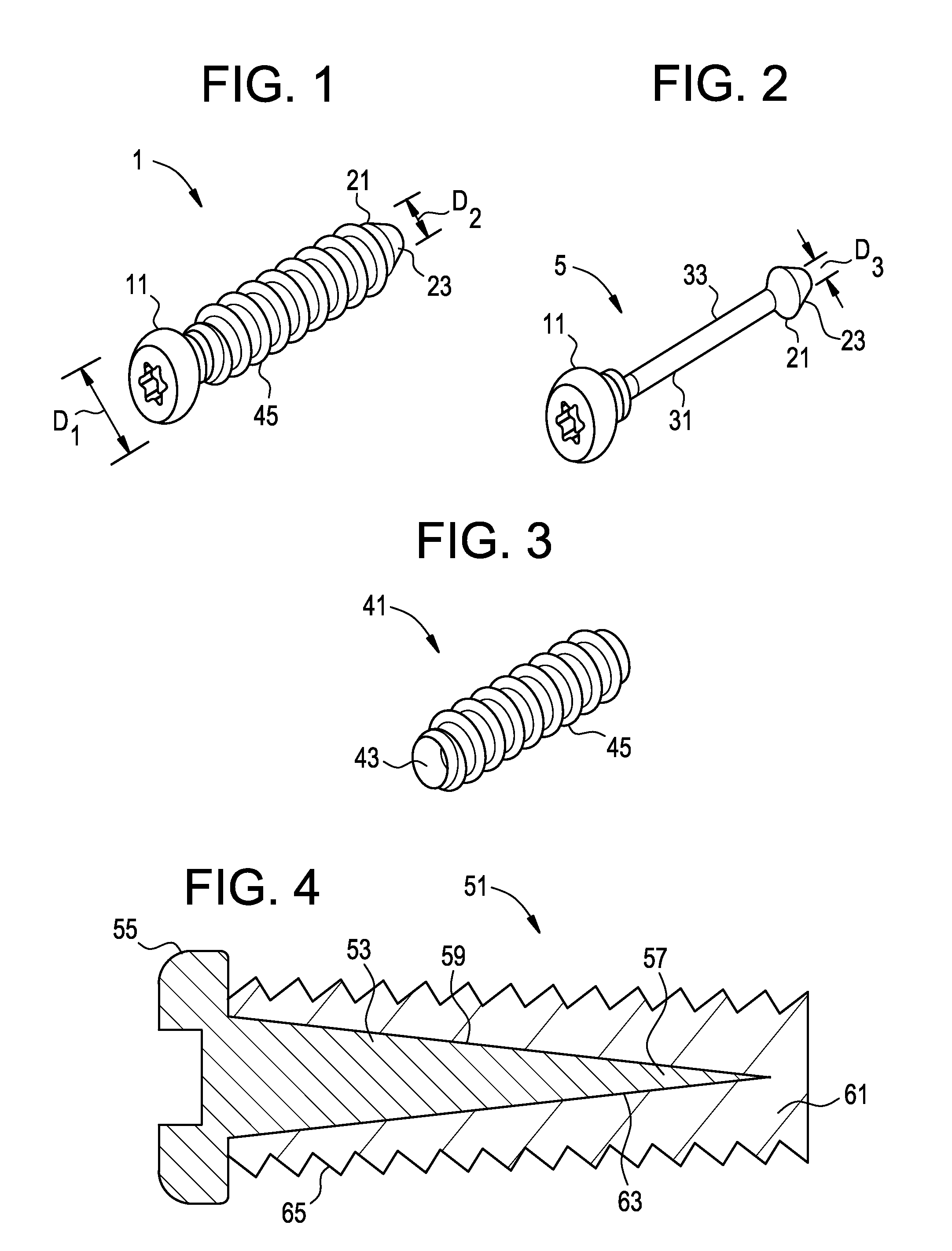
[0028]Referring now to FIGS. 1-3, there is provided a composite bone fixation system 1 comprising:[0029]i) a pin 5 comprising:[0030]a) a proximal head 11 having a first maximum diameter D1,[0031]b) a distal tip 21 having a second maximum diameter D2 and a distally narrowing insertion taper 23, and[0032]c) a substantially cylindrical intermediate shaft portion 31 having an outer surface 33 defining a third maximum diameter D3,[0033]ii) a threaded polymeric tube 41 comprising an inner bore 43 and a threaded outer surface 45,

wherein the threaded polymeric tube wraps around the outer surface of the substantially cylindrical intermediate shaft portion, and

wherein each of the first maximum diameter D1 and second maximum diameter D2 is greater than the third maximum diameter D3.

[0034]When each of the first maximum diameter D1 and second maximum diameter D2 is greater than the third maximum diameter D3, the polymeric tube (which circumferentially contacts the outer surface of the shaft and ...


PUM


Abstract

A composite screw preferably made of a metallic pin embedded in a polymeric tubular structure having the outwardly facing threads, wherein the metallic pin comprises a screw head, an intermediate shaft and a screw tip, and the polymeric threaded tube is either molded onto the metallic shaft or the threaded is machined after molding a polymeric structure onto the shaft.

Description

BACKGROUND OF THE INVENTION[0001]Pedicle screws used in spinal surgery are disclosed, for example, in U.S. Pat. No. 5,672,176.[0002]Spinal fixation devices are used in orthopedic surgery to align and / or fix a desired relationship between adjacent vertebral bodies. Such devices typically include a spinal fixation element, such as a relatively rigid fixation rod, that is coupled to adjacent vertebrae by attaching the element to various anchoring devices, such as hooks, bolts, wires, or screws. The fixation rods can have a predetermined contour that has been designed according to the properties of the target implantation site, and once installed, the instrument holds the vertebrae in a desired spatial relationship, either until desired healing or spinal fusion has taken place, or for some longer period of time.[0003]Spinal fixation devices can be anchored to specific portions of the vertebra. Since each vertebra varies in shape and size, a variety of anchoring devices have been develop...

Claims


Application Information

Patent Timeline
Patent Type & Authority Applications(United States)
IPC IPC(8): A61B17/86
CPCA61B17/8685A61B17/866
Inventor MOUMENE, MISSOUM
Owner DEPUY SYNTHES PROD INC
Why Eureka
Try Eureka