
Discharge head and droplet discharging device

a technology of droplet discharging device and discharge head, which is applied in the direction of inhalator, printing, other medical devices, etc., can solve the problems of durability, drug can be scorched by heat, and difficulty in increasing the discharge rate, and achieve the effect of small droplets and without raising the pressure necessary

Inactive Publication Date: 2010-04-08
CANON KK
View PDF14 Cites 23 Cited by
  • Summary
  • Abstract
  • Description
  • Claims
  • Application Information

AI Technical Summary

Benefits of technology

[0016]In view of the above-identified circumstances, it is therefore the object of the present invention to provide a discharge head and a droplet discharging device that can produce very small droplets than ever while maintaining the durability of the discharge head without raising the pressure necessary for discharging liquid.
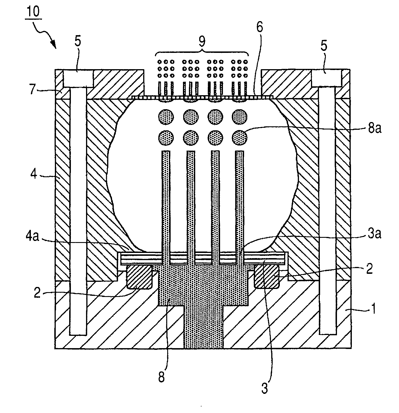
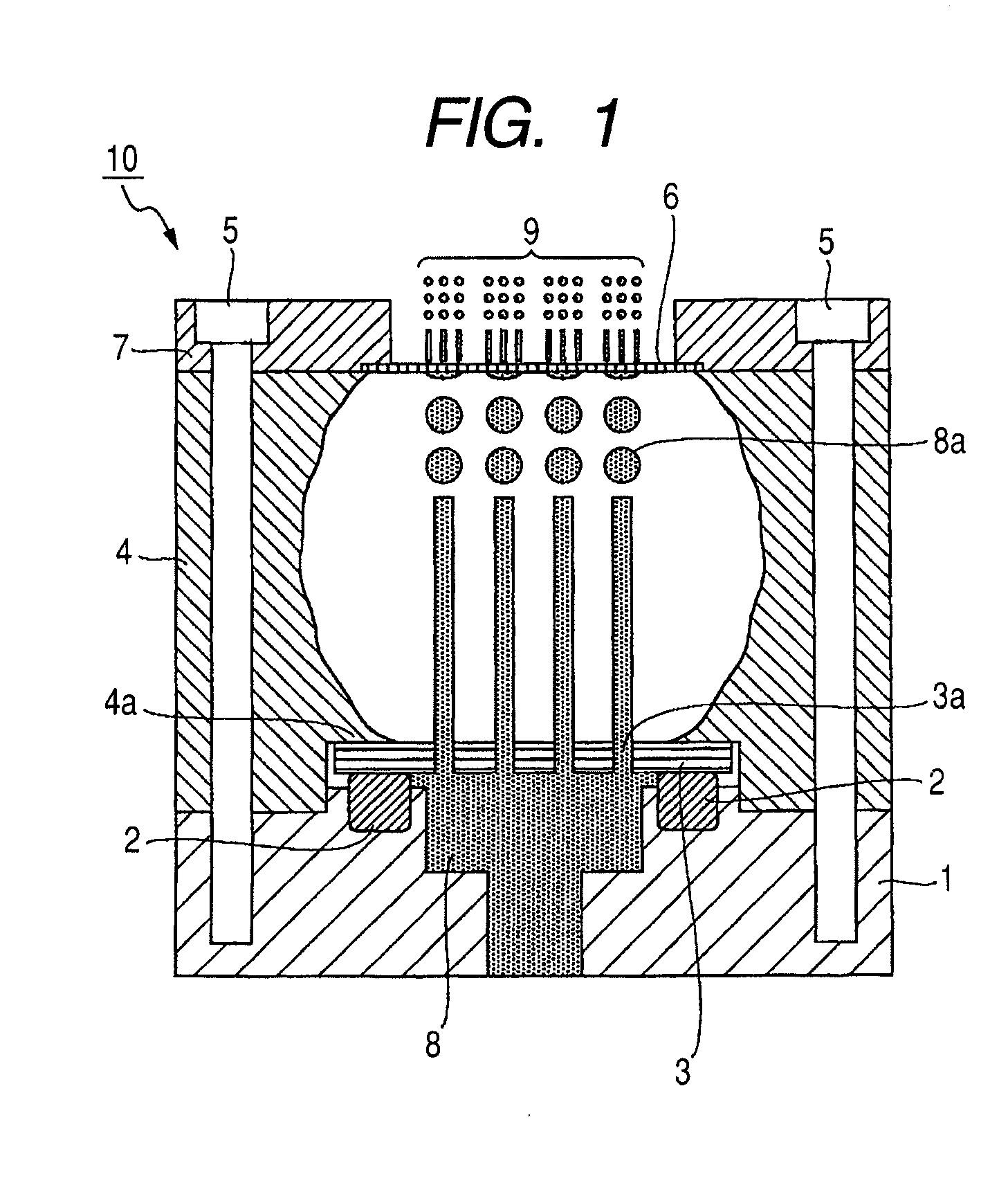
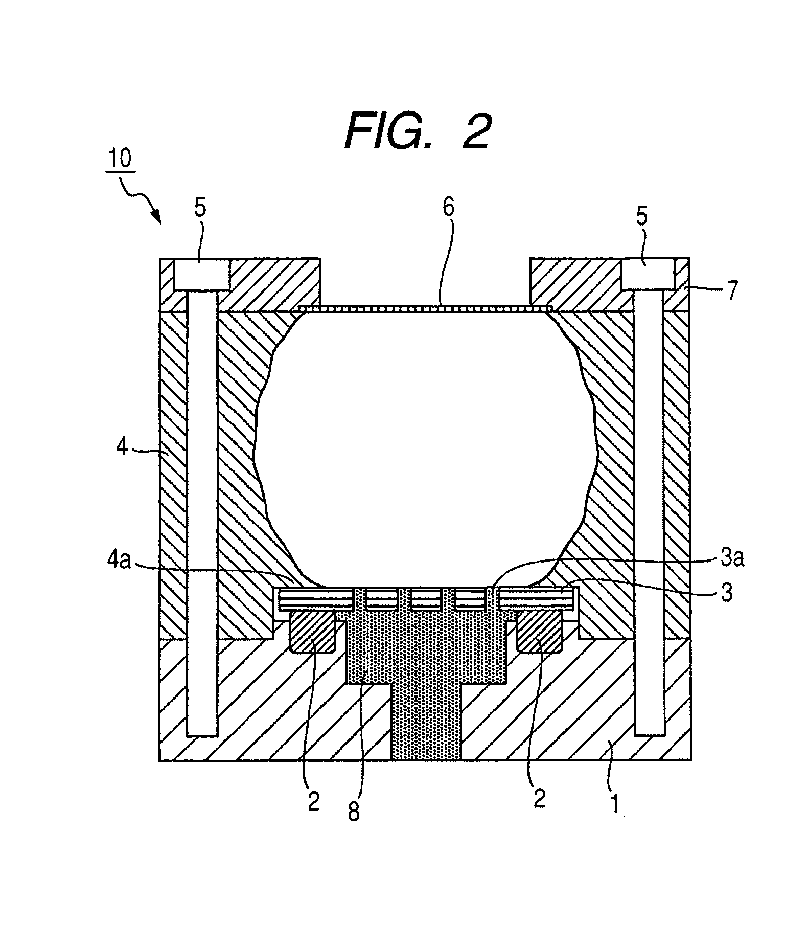
[0018]The arrangement of two orifice plates provides the advantage as described below. As the second orifice plate of the second discharge port diameter smaller than the first discharge port diameter is provided, the first discharge port diameter of the first orifice plate can be made larger than the diameter of the droplets to be produced. Then, as a result, it is not necessary to raise the discharge pressure. Thus, it is no longer necessary to make the first orifice plate thin and hence the discharge head can maintain a high degree of durability.

Problems solved by technology

While this method allows the inhaler to be downsized and droplets to be micronized with ease, it is accompanied by problems including that large power needs to be supplied to the heater to increase the discharge rate so that it is actually difficult to increase the discharge rate and that the drug can be scorched by heat.
Therefore, inhalers adopting a pressure exertion method are required to have a structure that can withstand high liquid pressure at the part thereof that is brought into contact with liquid medicine and also a mechanism for exerting high pressure so that they face a problem of durability and that of downsizing.
A single dose inhaler as disclosed in WO 94 / 27653 requires the cartridge to be replaced each time after drug administration to make the operation of the inhaler cumbersome and liable to induce an accident.
Additionally, the cost of the cartridge material rises.
However, the strength of the orifice plate is reduced when the orifice plate is made thin to make it difficult to bond the orifice plate and the discharge head.
Even if they can be bonded, the orifice plate can no longer withstand the high liquid pressure at the time of discharging the liquid medicine to give rise to liquid leakage from the junction and destroy the discharge head.
Additionally, the orifice plate itself will be deformed and destroyed under the high liquid pressure.
It is difficult for the conventional design of arranging an orifice plate at part of the container for containing solution under high water pressure as disclosed in WO 94 / 27653 to secure durability because the orifice plate is exposed to high water pressure for a long time when the discharge head is operated repeatedly.
However, durability does not give rise to a serious problem when the orifice plate is exposed to high water pressure only instantaneously in instances where the discharge head is disposable as disclosed in WO 94 / 27653.
Additionally, the problem that the durability of the discharge head is reduced as the orifice plate is made thinner to reduce the discharge pressure remains unsolved.

Method used


Image

  • Discharge head and droplet discharging device
  • Discharge head and droplet discharging device
  • Discharge head and droplet discharging device

Examples


example 1

[0084]An orifice plate same as that of the discharge head E1 (ruby-made, 500 μm-thick, having discharge ports of a diameter of 40 μm) was rigidly secured to a head base member as the first orifice plate illustrated in FIG. 1 by way of a seal member (O-ring). Additionally, an orifice plate same as that of the discharge head E5 (Ni-made, prepared by electroforming, 3 μm-thick, having discharge ports of a diameter of 5 μm) was bonded to a second plate securing member in the same manner. The distance separating the first orifice plate and the second orifice plate was 8 mm. It was confirmed that the liquid jets discharged from the first orifice plate were turned into droplets by the time they got to the second orifice plate.

Discharge Head 8

example 2

[0085]This discharge head had the same structure as the discharge head E7 except that an orifice plate which is the same as that of the discharge head E6 (Ni-made, prepared by electroforming, 3 μm-thick, having discharge ports of a diameter of 1.5 μm) was used as the second orifice plate.

[0086]Since the discharge head E1 and the discharge head E2 employed ruby-made orifice plates that were thick and hard, it was not possible to form discharge ports having a diameter not larger than 20 μm. While it was possible to form very fine discharge ports having a diameter not more than 5 μm through Ni thin film produced by electroforming, the strength of the thin film was remarkably low to make it difficult to rigidly secure the film to a head base member.

[0087]Then, refined water was selected as liquid to be discharged and the discharge heads E1 through E8 were operated to discharge droplets. The operations of discharging droplets were observed. As a result of the observation, it was found th...


PUM


Abstract

A discharge head 10 for discharging droplets from discharge ports can withstand high water pressure and is provided with a first orifice plate 3 having first discharge ports 3a and a second orifice plate 6 having second discharge ports. The first orifice plate 3 and the second orifice plate 6 are separated from each other in the liquid discharge direction of the discharge head 10 and disposed opposite to each other. The diameter of the discharge ports of the second orifice plate 6 is smaller than the diameter of the discharge ports 3a of the first orifice plate 3 so that very fine droplets 9 are discharged from the discharge head 10 as the liquid discharged from the discharge ports 3a of the first orifice plate 3 is split by the second discharge ports.

Description

BACKGROUND OF THE INVENTION[0001]1. Field of the Invention[0002]The present invention relates to a discharge head for discharging liquid such as liquid medicine and turning the liquid into liquid droplets and also to a droplet discharging device.[0003]2. Related Background Art[0004]A method of administering a drug to a patient by using an inhaler and causing the patient to inhale very fine droplets of the drug (liquid medicine) formed by dispersing the drug into a solution is known. Such an inhaler includes a reservoir for storing liquid medicine, a discharge head for discharging the liquid medicine and a control section for controlling the operation of each of the components. Particularly, for a patient to inhale liquid medicine by way of alveoli of the lung, droplets should be made to represent a diameter not greater than 10 μm so as to be able to get to alveoli. Therefore, the inhaler is required to be able to produce a large number of droplets having such a small droplet diamete...

Claims


Application Information

Patent Timeline
Patent Type & Authority Applications(United States)
IPC IPC(8): A61M11/00
CPCA61M11/041A61M15/0085A61M15/02A61M2202/0468A61M15/025B41J2/14B41J2/1433A61M11/003A61M2205/8206A61M11/005A61M11/042A61M15/008B05B17/0646B05B17/0638
Inventor FUKUMOTO, YOSHIYUKIKOBAYASHI, MASAYASUGITA, MASARU
Owner CANON KK
Learn More