Systems and Methods for Continuous Multiphase Reaction and Separation

Inactive Publication Date: 2010-04-08
GLOBAL BIO CHEM TECH GROUP
View PDF18 Cites 12 Cited by
  • Summary
  • Abstract
  • Description
  • Claims
  • Application Information

AI Technical Summary

Benefits of technology

[0024]In certain embodiments, the system further comprises a means for maintaining a substan

Problems solved by technology

The small sized catalysts, however, create a difficulty for their separation from a liquid product.
Efficient continuous separation of catalysts from a slurry phase within a reaction vessel is a challenging task for designing a slurry reactor.
The catalysts are prone to be broken down, and the pumps, valves, and pipes involved in the external slurry circulation loop are easily worn by the solid catalyst content (being oftentimes metal compounds).
These are obstacles to achieving the goal of a long term continuous operation, which is important for large-scale industrial production.
These circulation delivery elements may suffer from abrasion by catalysts (which are often metal compounds) and may need periodic cleaning or replacement.
In existing liquid / solid separation methods using internal filter unit, catalyst particles deposited on the filter units causes clogging over time.
The system disclosed in the '924 patent is only suitable for batched process because of the lack of a mechanism to prevent the common problem of catalyst deposition on the filter.
However, fixed-bed reactors have poor mass transport and thermal transfer, and the reaction temperature is difficult to control or stabilize.
This may lead to an exceeding high reaction temperature, which in turn leads to polymerization of either the reactant or the product.
The polymer thus produced may clog the pores in and between the catalyst particles.
The high temperature may also lead to change in the crystalline structure of the catalyst and shorten its active life.
If a slurry bed is used, mixing gas and liquid reactants is not easily achieved without an agitation device.
Continuous separation of a liquid product from a slurry in a slurry reactor in a continuous reaction operation has posed great challenges due to the breakdown of the catalyst particles into catalyst fines.
This may lead to the clogging of the liquid product separation device by the catalyst fines, making the separation decreasingly efficient over time, or the gradual loss of the catalyst in the slurry system as the catalyst fines permeate through the separation device and are withdrawn along with the liquid product.
Including liquid / solid separation devices in a reaction vessel decreases the volume available for reaction, and thus reduces productivity of the system.

Method used


Image

  • Systems and Methods for Continuous Multiphase Reaction and Separation
  • Systems and Methods for Continuous Multiphase Reaction and Separation
  • Systems and Methods for Continuous Multiphase Reaction and Separation

Examples


example 1

Sorbitol Hydrogenolysis

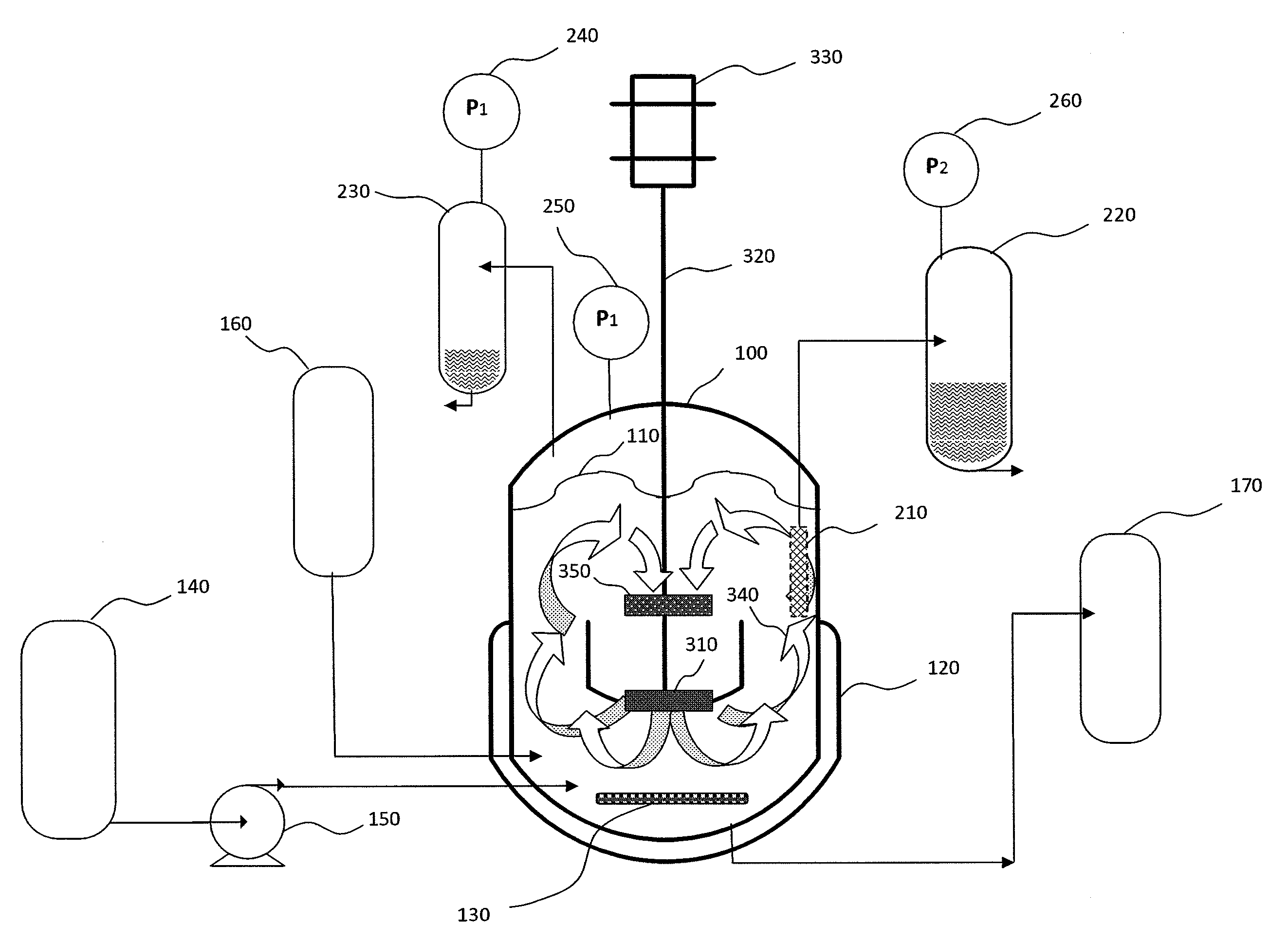
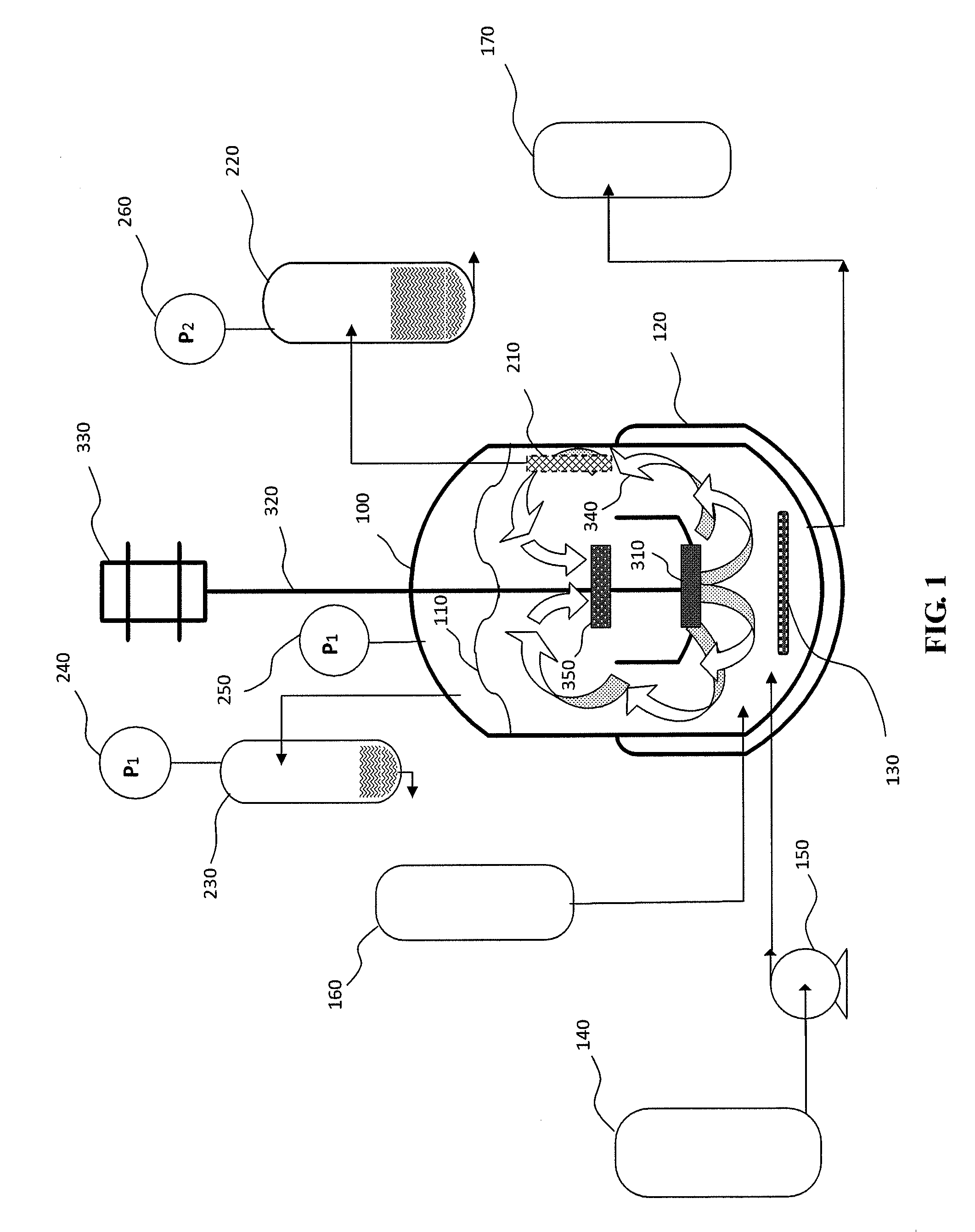
[0049]This Example illustrates the results of certain embodiments of the present invention as used in a continuous reaction / separation for sorbitol hydrogenolysis, the reactants of which include sorbitol and hydrogen gas. The conditions and results of 3 experiment setups, i.e., at laboratory scale, intermediate scale, and production scale for sorbitol hydrogenolysis are provided in the following Table 1. At the production scale, sorbitol hydrogenolysis was run for 6 months without interruption, during which time the temperature of the reaction system was kept stable, and no decreased efficiency of the separation device was observed. The pressure differential was kept substantially constant and the average catalyst activity and selectivity were also maintained substantially constant.

TABLE 1Conditions for sorbitol hydrogenolysisLaboratoryIntermediateProductionscaleScaleScaleVolume of the reaction vessel0.01730(m3)Total Surface Area of Separation0.004116~2060Devi...

example 2

Mixed Polyol Hydrogenolysis

[0050]In this Example, an intermediate scale experiment setup was employed, where the volume of the reaction vessel was 7 m3, and the aggregate surface area of the filters was 16.2 m2. The reaction / separation was run continuously for 132 days, but in three stages. In the first 40 days, the reactants were sorbitol and hydrogen gas; from Day 41 to Day 80, the liquid reactant was changed to mixed polyols including sorbitol and glycerol, as well as their dimers, trimers and tetramers. On Day 81, the liquid reactant was switched back to pure sorbitol, and the reaction was continued till the end of Day 132. During the course of the 132-day period, the flux across the separation device was maintained at a constant of 2.45 m3 / h, while the pressure differential was adjusted dynamically in the range of 0.20 bar to 0.40 bar to help maintain the constant flux. This constant flux roughly corresponded to the feeding rate of the liquid reactant(s) in the relevant stages....


PUM

PropertyMeasurementUnit
Timeaaaaaaaaaa
Thicknessaaaaaaaaaa
Pressureaaaaaaaaaa

Abstract

The present invention relates to a slurry reactor system suitable for continuous multiphase reaction / separation, as well as a method for continuous reaction / separation of a multiphase reaction in a slurry reactor system. The system includes a reaction vessel, a separation device that includes a separation chamber and a filter element, and an agitation device. The filter element includes a filter, which is in contact with a slurry in the reaction vessel and on the surface of which a solid material from the slurry forms a filter cake in the reaction vessel. The agitation device generates a flow of the slurry in the reaction vessel. A flux of a liquid product from the slurry in the reaction vessel across the filter and into the separation chamber is maintained at a substantially constant level for long term continuous reaction / separation without interruption.

Description

FIELD OF INVENTION[0001]The present invention relates to a slurry reactor system suitable for continuous multiphase reaction / separation. The present invention also relates to a method for continuous reaction / separation of a multiphase reaction in a slurry reactor system.BACKGROUND OF THE INVENTION[0002]Slurry reactors are a common type of reactors designed for gas-liquid-solid three-phase reactions. They usually have large volumes to accommodate the reactants (and products) and can effectively remove the heat generated in highly exothermic catalytic reactions to ensure stable operations.[0003]The solid phase in a slurry reactor is often composed of catalyst particles used in the relevant reaction. To minimize the inhomogeneity of their dispersion and to increase the contact area between the catalysts and the reactants, it is desirable to use catalysts with small particle sizes, for example, in the order of tens of microns or even smaller. The small sized catalysts, however, create a...

Claims


Application Information

Patent Timeline
IPC IPC(8): B01D37/04
CPCB01J4/004B01J8/006B01J8/10B01J8/222B01J8/226B01J19/0066C10G2300/4056B01J2208/0015B01J2208/00539B01J2208/00548B01J2208/00867B01J2219/00779C10G2/342B01J19/18B01D35/00
Inventor LIU, JINGQI, HONGBINXU, ZHOUWEN
Owner GLOBAL BIO CHEM TECH GROUP
Why Eureka
Try Eureka