Crystal oscillator piece and method for manufacturing the same

a technology of crystal oscillator and manufacturing method, which is applied in the direction of instrument, device material selection, device details, etc., can solve the problems of leakage vibration generation, suppress leakage vibration generation, and reduce the relative value of leakage output.

Inactive Publication Date: 2010-04-08
CITIZEN WATCH CO LTD
View PDF1 Cites 8 Cited by
  • Summary
  • Abstract
  • Description
  • Claims
  • Application Information

AI Technical Summary

Benefits of technology

[0043]On the other hand, when etching is performed only from one side or, as shown in FIG. 11, using the upper surface pattern as the reference, the problem of the positional displacement between the upper etching mask and the lower etching mask does not arise, but since the angle at which the residue is formed on one side face is different from the angle at which the residue is formed on the other side face, the cross-sectional shape is not symmetrical, and when the direction of the principal axis is calculated, the cross section does not have a principal axis parallel to the X axis. This method can constantly produce oscillator pieces of uniform quality and is therefore effective in achieving resonant frequency stability, but it is not suited for the purpose of achieving an oscillator piece subs...

Problems solved by technology

On the other hand, if the principal axis is tilted away from the X axis toward the Z′ axis, since the direction of the bending force does not coin...

Method used


Image

  • Crystal oscillator piece and method for manufacturing the same
  • Crystal oscillator piece and method for manufacturing the same
  • Crystal oscillator piece and method for manufacturing the same

Examples


Embodiment Construction

[0084]A crystal oscillator piece according to the present invention and a method for manufacturing the same will be described below with reference to the drawings. It should, however, be noted that the technical scope of the present invention is not limited to the specific embodiments described herein, but extends to the inventions described in the appended claims and their equivalents.

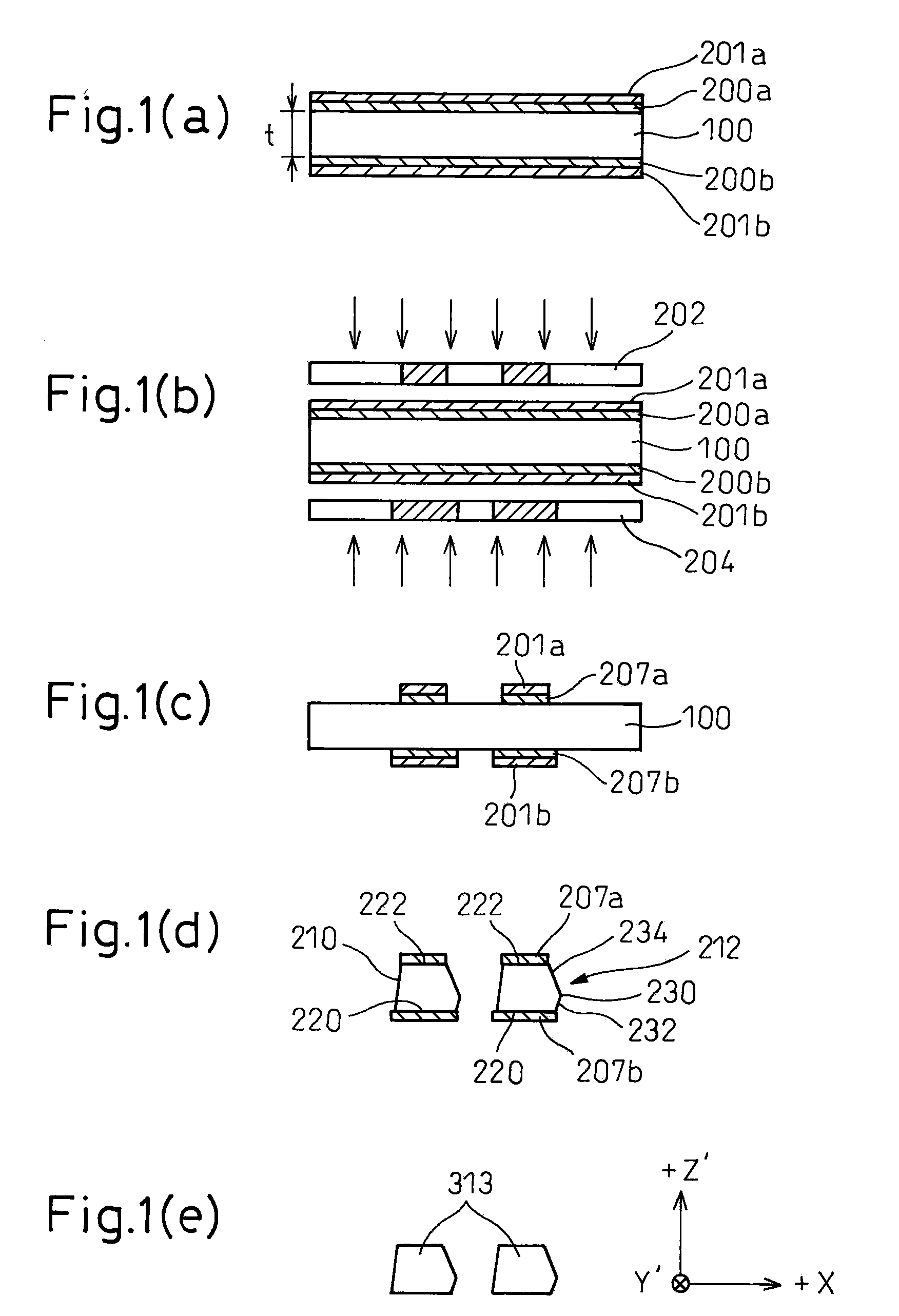
[0085]First, the method for manufacturing the crystal oscillator piece according to the present invention will be described with reference to FIG. 1.

[0086]FIG. 1(a) shows the condition in which corrosion resistant metal films 200a and 200b are formed by such means as sputtering, evaporation, or plating on the upper and lower surfaces of a crystal wafer 100 prepared to a thickness t. The corrosion resistant metal films 200a and 200b can each be formed using Cr for the base layer and Au or the like for the top layer. Photoresist films 201a and 201b are applied over the surfaces of the respective corrosi...


PUM

PropertyMeasurementUnit
Lengthaaaaaaaaaa
Thicknessaaaaaaaaaa
Widthaaaaaaaaaa

Abstract

An object of the present invention is to provide a crystal oscillator piece in which the generation of leakage vibration is suppressed, and a method for manufacturing such a crystal oscillator piece. More specifically, a method for manufacturing a crystal oscillator piece according to the present invention includes the steps of forming a first etching mask on an upper surface of a crystal wafer and a second etching mask on a lower surface of the crystal wafer, and forming a vibrating tine by immersing the crystal wafer in an etching solution thereby dissolving crystal portions not covered with the first and second etching masks, wherein the second etching mask is designed to have a first protruding portion protruding from a position corresponding to a first edge of the first etching mask, the first protruding portion being chosen to have such a length that a first residue is formed in a predetermined shape on a first side face, irrespective of a positional displacement between the first and second etching masks, and wherein the first and second etching masks are designed so that a second residue formed on a second side face is adjusted so as to ensure that one of two principal axes passing through a centroid and dynamically perpendicular to each other in a cross section taken perpendicularly to a longitudinal direction of the vibrating tine is oriented substantially parallel to the upper or lower surface of the crystal wafer.

Description

FIELD OF THE INVENTION[0001]The present invention relates to a crystal oscillator piece and a method for manufacturing the same, and more particularly to a crystal oscillator piece that has a structure for suppressing the occurrence of leakage vibration correspond to out-of-plane vibration, and a method for manufacturing such a crystal oscillator piece.BACKGROUND OF THE INVENTION[0002]A tuning fork crystal oscillator used for a vibratory gyro is manufactured by the steps of cutting a crystal oscillator piece to a desired shape from a crystal wafer, forming electrodes for causing the crystal oscillator piece to oscillate, and packaging the crystal oscillator piece with the electrodes formed thereon into a container. Of these steps, the step of cutting the crystal oscillator piece from a crystal wafer is particularly important because the shape of the crystal oscillator piece determines the motion of vibration and greatly affects the device performance.[0003]FIG. 8 is a diagram showin...

Claims


Application Information

Patent Timeline
IPC IPC(8): H01L41/04H01L41/22H01L41/09H01L41/18H01L41/332H03H3/02H03H9/19H03H9/215
CPCG01C19/5607H03H3/04H03H9/02086Y10T29/42H03H9/215H03H2003/026H03H9/02149
Inventor KATOH, AKIKOMORIYA, TAKASHI
Owner CITIZEN WATCH CO LTD
Why Eureka
Try Eureka