Method and System for Rendering 3D Distance Fields

Active Publication Date: 2010-04-08
MITSUBISHI ELECTRIC RES LAB INC
View PDF22 Cites 40 Cited by
  • Summary
  • Abstract
  • Description
  • Claims
  • Application Information

AI Technical Summary

Problems solved by technology

However, it can be difficult to create images without holes.
Uniform coverage of the surface with points is not guaranteed and considerable effort is required to identify and fill in missing regions.
The process of identifying surface cells in the octree that contain the surface along the direction of the cast ray is fairly simple, but can be very inefficient in terms of computer memory accesses.
The data associated with spatially adjacent cells in the octree are often widely separated in computer memory, resulting in a high rate of CPU memory cache misses, which degrades the overall performance of the rendering method.
When the data required for casting rays through a cell are not in the CPU cache as needed, the rendering update rate is severely decreased, sometimes to the point that in

Method used


Image

  • Method and System for Rendering 3D Distance Fields
  • Method and System for Rendering 3D Distance Fields
  • Method and System for Rendering 3D Distance Fields

Examples


Embodiment Construction

[0045]Method and System Overview

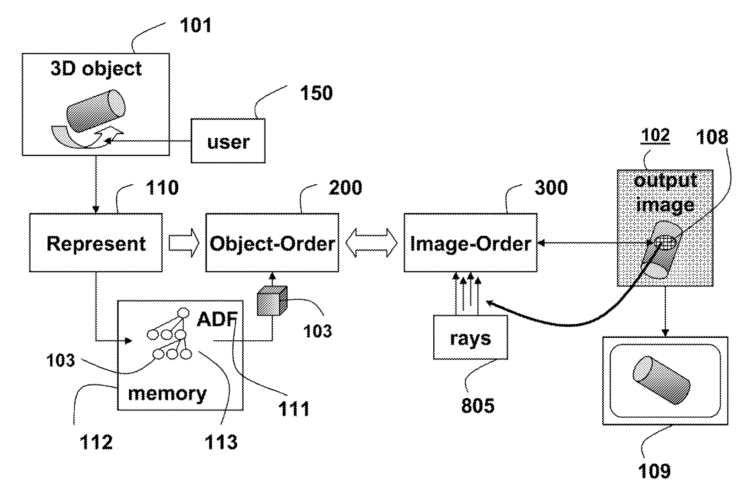
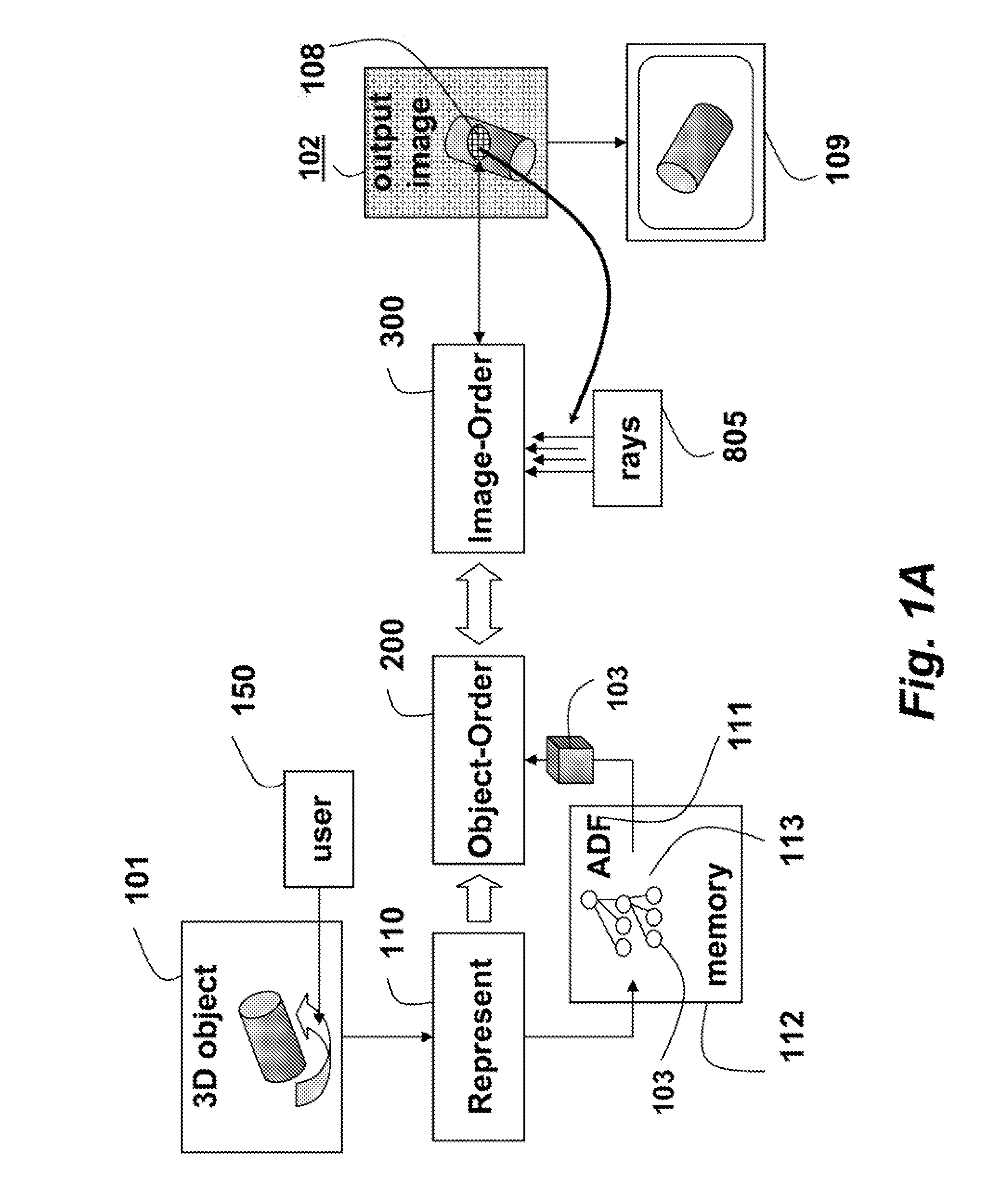
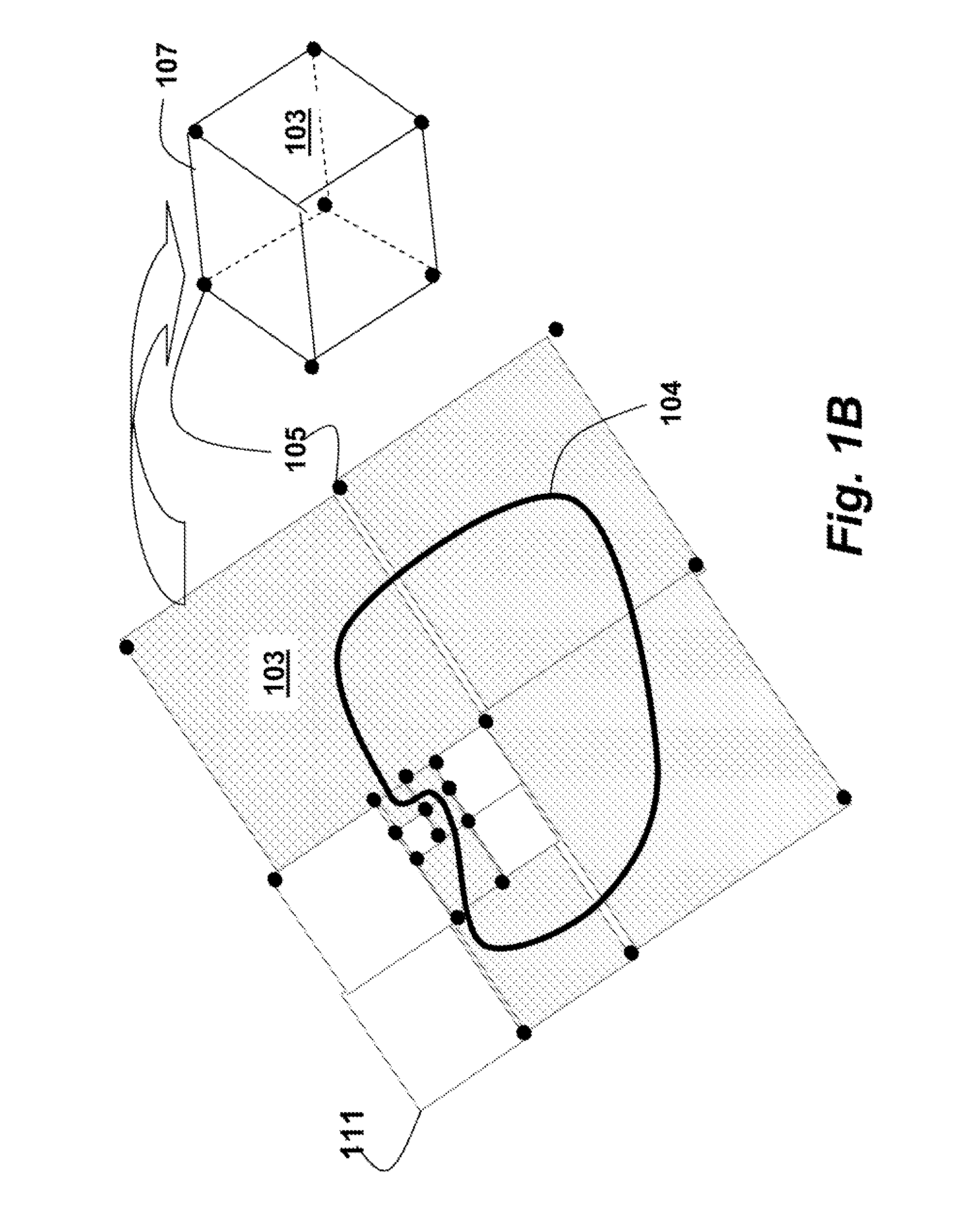
[0046]As shown in FIGS. 1A-1B, the embodiments of our invention provide a method for rendering a 3D model 111 of a 3D object 101 as an output image 102. The rendering can be to a display or print device 109, or a memory. FIG. 1A shows the method and FIG. 1B shows a cell-based data structure. The rendering can simulate machining operations such as performed by a milling machine, as shown in FIG. 9.

[0047]In one embodiment of the invention, the model represents the object as a 3D adaptively sampled distance field (ADF) stored in a memory 112 of a computer system as an octree 113. However, in general, the model can be any distance field structurally represented as a space partitioning data structure, for example a k-dimensional tree, or an octree. Additionally, the distance field can be reconstructed from distance field samples, or determined analytically by, for example, a continuous function.

[0048]When the distance field is stored in an octree data stru...


PUM


Abstract

A method and system renders a 3D model of a 3D object as an image including image samples. The 3D model is a distance field, and the distance field includes surface cells representing portions of a surface of the 3D object. A set of image samples in the image is determined in an object-order phase for each surface cell. Each surface cell is then processed independent of other surface cells. The processing casts a ray, in an image order phase from each image sample in the set of image samples, through the surface cell to determine a contribution of the surface cell to the image sample, and then the image is rendered.

Description

FIELD OF THE INVENTION[0001]This invention relates generally to the field of computer graphics and to rendering 3D models of 3D objects, and more particularly to rendering the 3D models of the 3D objects where the 3D models are represented as 3D distance fields, and used to simulate the results of computer numerically controlled (CNC) machining operations.BACKGROUND OF THE INVENTION[0002]Distance Fields[0003]In computer graphics applications, a three-dimensional (3D) object can be represented using a number of different methods, e.g., methods that use polygonal models, point cloud models, parametric functions, or implicit functions.[0004]One class of methods uses a distance field that specifies a minimum distance d(x) from any location x=(x, y, z) in 3D space to a surface of the object. The distance field d(x) can distinguish the inside, the outside and the surface of the object, e.g., d(x)<0 is outside, d(x)>0 is inside, and d(x)=0 is on the surface of the object.[0005]Furthe...

Claims


Application Information

Patent Timeline
IPC IPC(8): G06T17/00G06T15/06G06T15/08
CPCG06T15/08G06T15/06G06T17/00G06T17/005G06T17/10G06T17/20G06T19/00
Inventor SULLIVAN, ALANFRISKEN, SARAH F.PERRY, RONALD N.
Owner MITSUBISHI ELECTRIC RES LAB INC
Why Eureka
Try Eureka