Electrical connector

a technology of electrical connectors and connectors, applied in the direction of coupling device connections, electrical discharge lamps, coupling device details, etc., can solve the problems of increasing the difficulty of problems, reducing the processing ability of incoming signals, and compounding problems

Inactive Publication Date: 2010-04-08
COMMSCOPE TECH LLC
View PDF63 Cites 21 Cited by
  • Summary
  • Abstract
  • Description
  • Claims
  • Application Information

AI Technical Summary

Problems solved by technology

Signal coupling, ie crosstalk, between different pairs of wire paths in the jack is a source of interference that degrades the ability to process incoming signals.
The higher the data rate, the greater difficulty of the problem.
These problems are compounded because of international standards that assign the wire pairs to specified terminals.
The pair assignment leads to difficulties when high frequency signals are present on the wire pairs.
Many electrical connectors that receive modular plugs are configured that way, and although the amount of crosstalk between pairs 1 and 3 is insignificant in the audio frequency band, it is unacceptably high at frequencies above 1 MHz.
Still, it is desirable to use modular plugs and jacks of this type at these higher frequencies because of connection convenience and cost.
While these approaches to reducing cross talk may be useful, they may not be sufficient to satisfy the ANSI / TIA / EIA-568-B.2-1 standard for Gigabit Ethernet (the so-called “Category 6” cabling standard).
The high-frequency operation demanded from the Category 6 standard also produces problems for the connectors and jacks used to connect any two Category 6 cables.
The dielectric material has previously exotic or expensive.
The cost of the dielectric material may increase the cost of manufacturing capacitors.
Capacitors obtained from external sources can often have severe limitations, or have large margins of error.
As such, they may not be suitable for high-accuracy applications.

Method used


Image

  • Electrical connector
  • Electrical connector
  • Electrical connector

Examples


Embodiment Construction

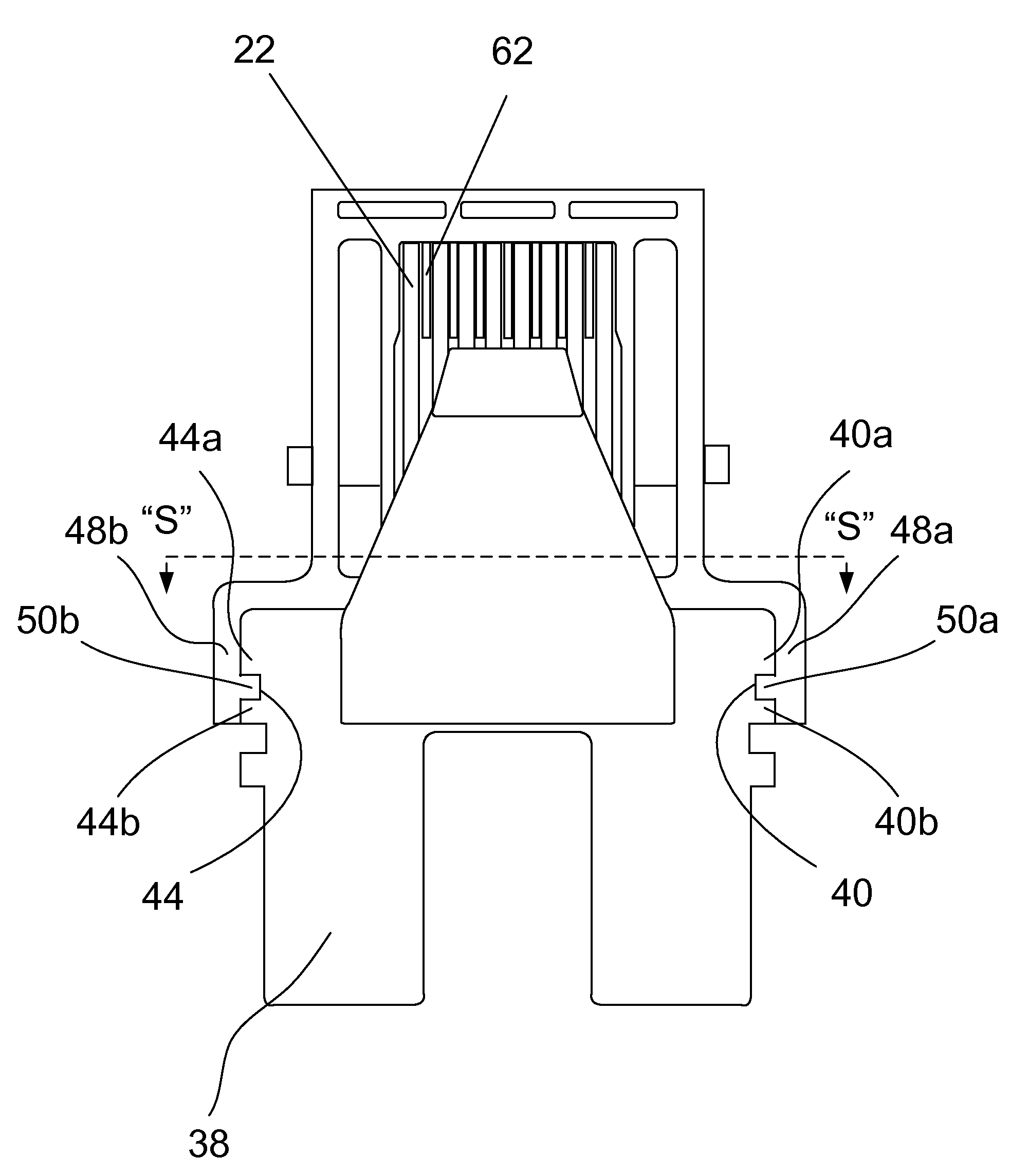
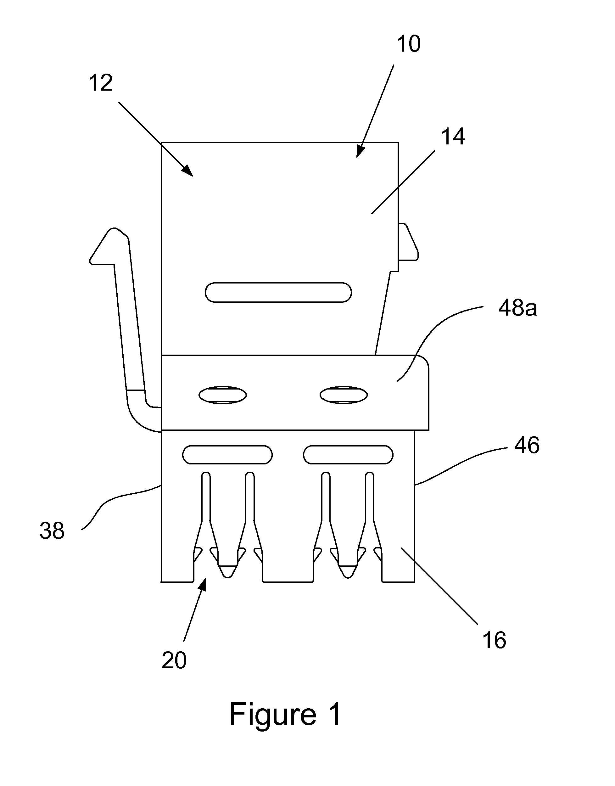
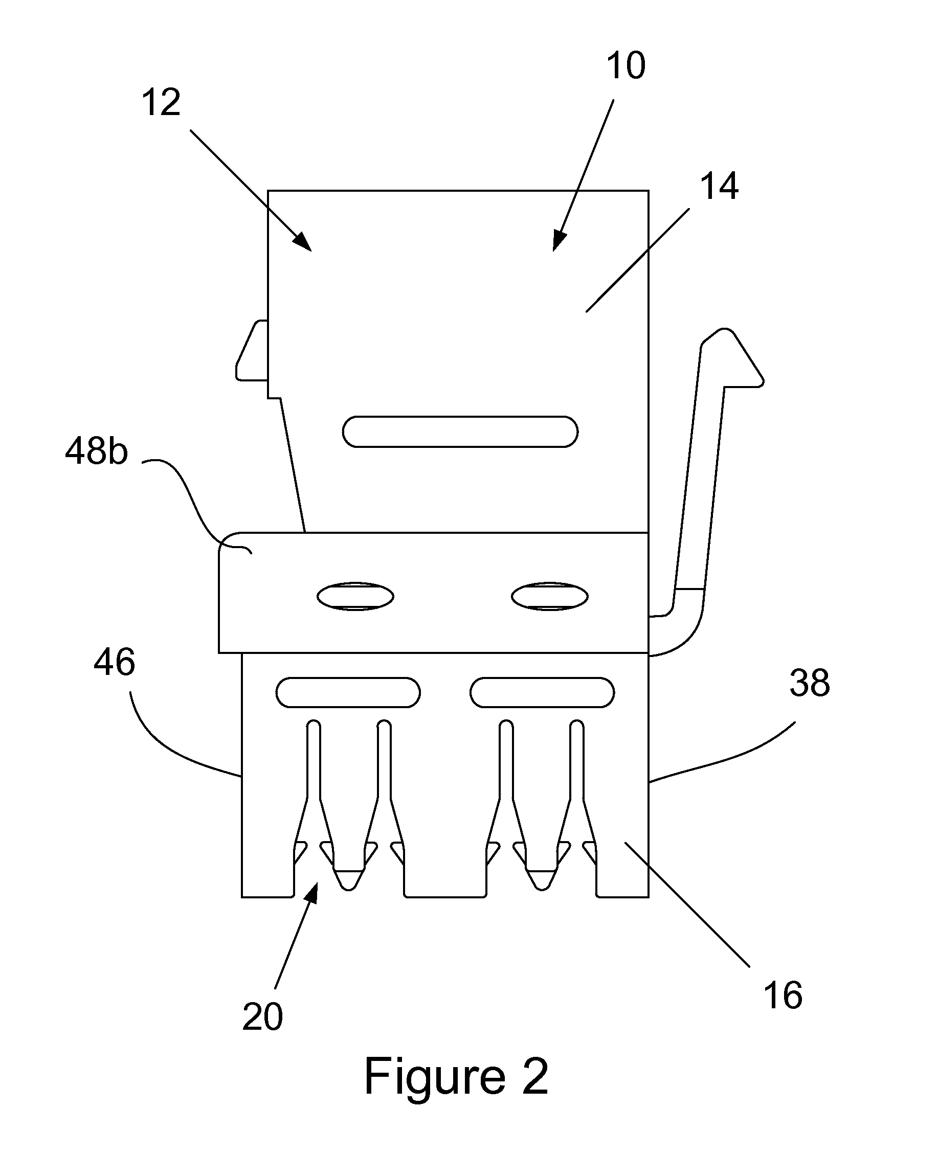
[0063]The electrical connector 10, also referred to as the Jack 10, shown in FIGS. 1 to 6 includes a housing 12 formed in front 14 and back 16 interlocking parts. The front part 14 of the housing 12 includes a socket 18 that is shaped to at least partially receive a male section of a modular plug (not shown) that terminates the insulated conductors of an electric data cable. The back part 16 of the housing 12 includes insulation displacement contact slots 20 that are each shaped to receive an end section of an insulated conductor of an electronic data cable (not shown).

[0064]The electrical connector 10 also includes eight electrically conductive contact elements 22, as shown in FIGS. 7 to 11, that each extend between the socket 18 and corresponding insulation displacement contact slots 20. The contact elements 22 electrically connect conductors of a first electronic data cable connected to the socket 18 to corresponding conductors of another electronic data cable coupled to respecti...


PUM


Abstract

An electrical connector for transmitting data signals between the insulated conductors of a first data cable and corresponding insulated conductors of a second data cable, including a first part having a socket shaped to at least partially receive a plug of said first data cable; a second part having a plurality of insulation displacement contact slots shaped to receive end sections of the conductors of the second data cable; a plurality of electrically conductive contacts including resiliently compressible spring finger contacts extending into the socket for electrical connection with corresponding conductors of the first cable; insulation displacement contacts seated in corresponding insulation displacement contact slots for effecting electrical connection with corresponding conductors of the second data cable; and mid sections extending therebetween; and a plurality of capacitive plates coupled to respective ones of said mid sections of the contacts by electrically conductive stems, wherein the capacitive plates are arranged side by side, extend in a substantially common direction, and are separated by a dielectric material extending at least partially therebetween.

Description

TECHNICAL FIELD OF THE INVENTION[0001]The present invention relates to an electrical connector.BACKGROUND OF THE INVENTION[0002]The international community has agreed to a set of architectural standards for intermatability of electrical connectors for the telecommunications industry. The connectors that are most commonly used are modular plugs and jacks that facilitate interconnection of electronic data cables, for example.[0003]A plug typically includes a generally rectangular housing having an end section shaped for at least partial insertion into a socket of a corresponding jack. The plug includes a plurality of contact elements electrically connected to the insulated conductors of an electronic data cable. The contact elements extend through the housing so that free ends thereof are arranged in parallel on an outer peripheral surface of the end section of the plug. The other end of the cable may be connected to a telephone handset, for example.[0004]A jack may be mounted to a wa...

Claims


Application Information

Patent Timeline
Patent Type & Authority Applications(United States)
IPC IPC(8): H01R33/00
CPCH01R13/6625H01R9/031
Inventor HOGUE, JASON ALLANSIELAFF, MICHAEL
Owner COMMSCOPE TECH LLC
Why Eureka
Try Eureka