Electrotherapeutic device

Inactive Publication Date: 2010-04-08
KONINKLIJKE PHILIPS ELECTRONICS NV
View PDF7 Cites 45 Cited by
  • Summary
  • Abstract
  • Description
  • Claims
  • Application Information

AI Technical Summary

Benefits of technology

[0005]It is an object of the present invention to provide a device of the kind mentioned above t

Problems solved by technology

However, the known device is not always suitable for use by non-professional users.
In general, a disad

Method used


Image

  • Electrotherapeutic device
  • Electrotherapeutic device
  • Electrotherapeutic device

Examples


Example

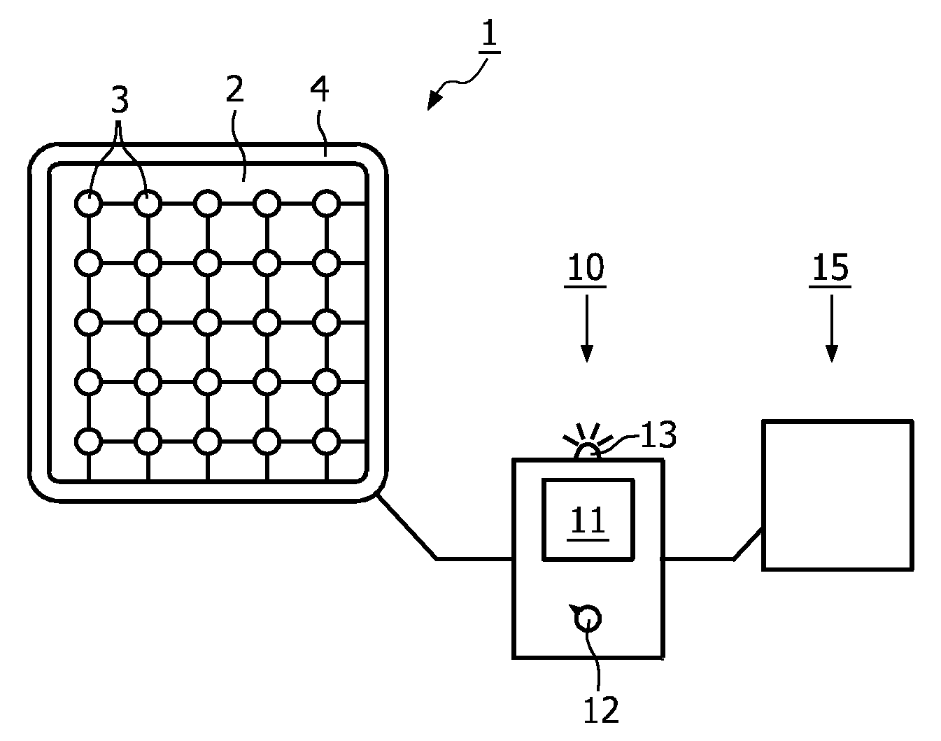
[0043]FIG. 1 shows a diagram of an electro-therapeutic device according to the invention.

[0044]Herein, 1 denotes an electrode unit, 10 denotes a control unit and 15 denotes a memory device. The electrode unit 1 comprises a pad 2 and a matrix of electrodes 3, with a counterelectrode 4. The pad 2 comprises preferably an electrically insulating material such as most plastics. Advantageously, it is a skin-friendly material. An example is polyethylene. Shown here is a grid of 5×5=25 electrodes 3. Any other desired number is also possible. Furthermore, the grid is a square grid. If desired, any other pattern in which the mutual position of electrodes 3 is known is also possible. Note that the electrodes are not directly mutually electrically connected but each is connectable to the control unit 10.

[0045]The counterelectrode 4 could also be provided around the individual electrodes 3, or therebetween. In fact, the counterelectrode 4 is optional since each of the electrodes 3 could also ser...


PUM


Abstract

The invention provides an electro-therapeutic device for application on a human or animal body part, comprising electrodes (3), a measuring means connected thereto and arranged to measure a value of an electrical quantity, and a control unit (10) to process the measured values, wherein the control unit (10) further comprises pattern recognition means to determine a pattern in the measured values, for example by comparing with patterns stored in a memory unit (15). By means of the determined pattern, the device is able to know its position on the body, and to determine whether this position is suitable for a treatment, and to which electrodes a treatment signal must be supplied. The device is much easier to use since it does not require any user's knowledge about patterns, as this may be stored in the device itself.

Description

FIELD OF THE INVENTION[0001]The present invention generally relates to electro-therapeutic devices. In particular, the present invention relates to an electrotherapeutic device, comprising a plurality of electrodes, measuring means operably electrically connected to the plurality of electrodes and arranged to measure a value of an electrical quantity for each of a plurality of said electrodes, and a control unit coupled to the measuring means and arranged to process the measured values.[0002]The device can be used as a professional or consumer product for pain relief in the medical and paramedical field.BACKGROUND OF THE INVENTION[0003]Document U.S. Pat. No. 6,301,500 discloses an electro-stimulation apparatus using an electrode matrix with a counterelectrode. The electrodes can measure local electrical impedance, and may also be used to provide electro-stimulation.[0004]However, the known device is not always suitable for use by non-professional users. It still requires knowledge t...

Claims


Application Information

Patent Timeline
IPC IPC(8): A61N1/04
CPCA61B5/0531A61B5/063A61H39/002A61H39/02A61N1/0456A61N2001/083A61N1/0484A61N1/0492A61N1/32A61N1/36021A61N1/0476A61N1/3603
Inventor VAN HERK, JOHANNES JOHANNAVAN LIESHOUT, MARJOLEIN IRENEWAGEMAKERS, FEMKEKOLEN, ALEXANDER FRANCISCUSBODLAENDER, MAARTEN PETERDROST, MIRELVA MARIA
Owner KONINKLIJKE PHILIPS ELECTRONICS NV
Why Eureka
Try Eureka