Pseudo-analytical method for the solution of wave equations

a wave equation and analytical method technology, applied in the field of geophysical subsurface imaging, can solve the problems of increased computational cost, high memory use, and high computational cost, and achieve the effects of high accuracy, easy interpolation, and improved accuracy

Active Publication Date: 2010-04-08
BP CORP NORTH AMERICA INC
View PDF12 Cites 93 Cited by
  • Summary
  • Abstract
  • Description
  • Claims
  • Application Information

AI Technical Summary

Benefits of technology

[0013]According to a first preferred embodiment, there is provided a method of seismic processing that utilizes a pseudo-differential space-domain operator in connection with a (preferably) second-order time-marching finite-difference method to solve the 1, 2, or 3-dimensional, etc., constant-velocity constant-density acoustic wave equation to near analytical accuracy. For the acoustic wave equation, ...

Problems solved by technology

Thus, this approach can lead to high memory use and high computational cost if high accuracy is desired.
High (spatial) order accurate methods use more than just the neighboring grid points to estimate the required spatial derivatives, which, of course, leads to increased computational cost.
The design process of the spatial difference coefficients assumes that infinitesimally small time steps are taken, which in practice is not true, and for cost reasons certainly not desirable.
This is unfortunate because in most cases (certainly for all second-order-accurate time-marching methods) the “sense” of the error caused by ...

Method used


Image

  • Pseudo-analytical method for the solution of wave equations
  • Pseudo-analytical method for the solution of wave equations
  • Pseudo-analytical method for the solution of wave equations

Examples


Embodiment Construction

[0021]While the inventive system and methods have been described and illustrated herein by reference to certain preferred embodiments in relation to the drawings attached hereto, various changes and further modifications, apart from those shown or suggested herein, may be made therein by those skilled in the art, without departing from the spirit of the inventive concept, the scope of which is to be determined by the following claims.

General Environment of the Invention

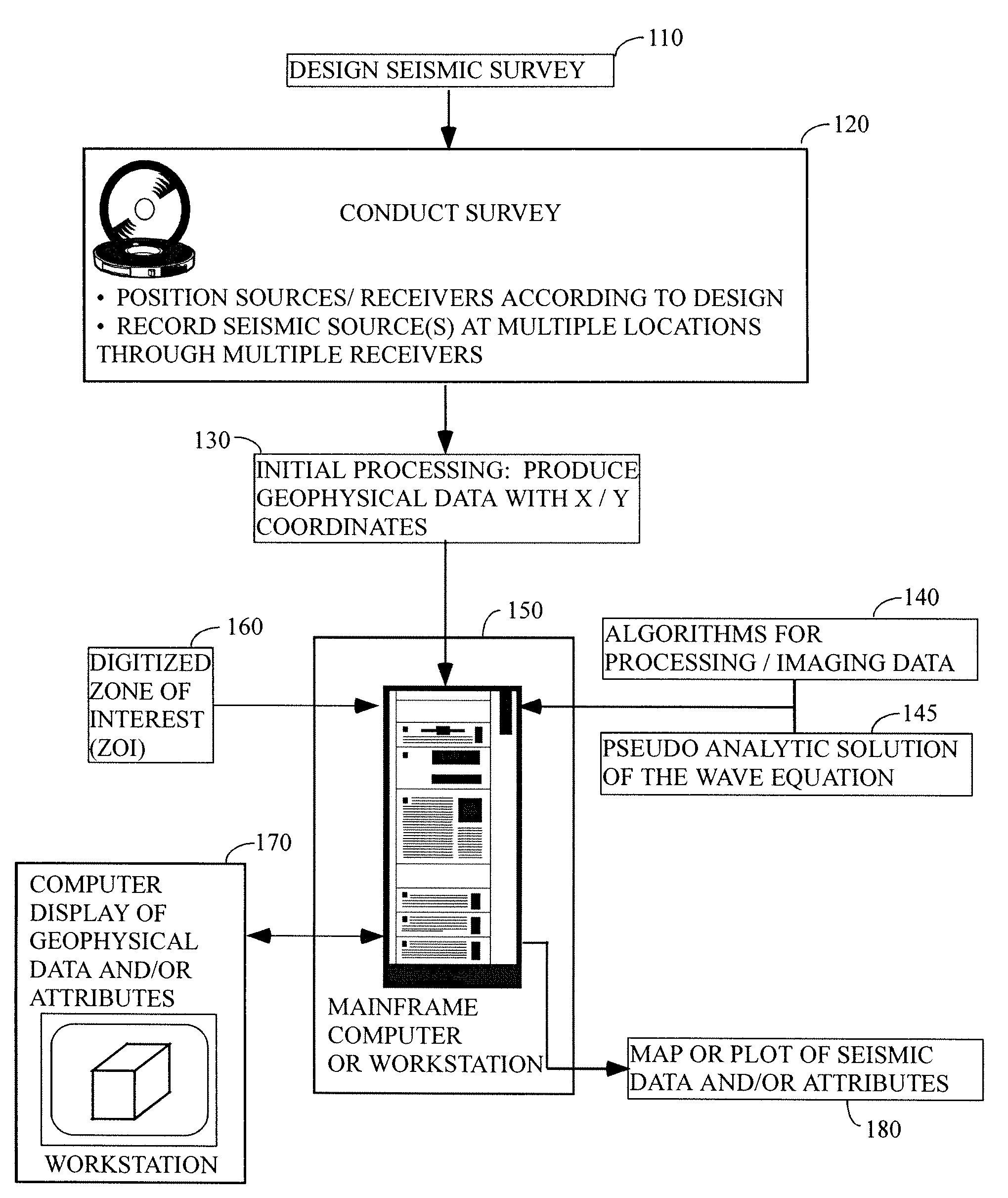
[0022]FIG. 1 illustrates the general environment in which the instant invention would typically be used. As a first step, a seismic survey will be designed (step 110), wherein the survey geometry, sample rate, number of sources / receivers, etc. would typically be selected in order to image a preferred subsurface target. Among the many parameters that might be considered in formulating the survey design are:[0023]the surface area to be covered by the survey;[0024]whether the survey will be conducted on land, offshore, o...


PUM


Abstract

The instant invention is a method for numerically propagating waves or solving wave equations on a digital computer. This invention can be used to compute highly accurate solutions to the wave equation, in fact in some cases it computes the analytical solution, something previously considered impossible. The instant method can also propagate waves that are not described by differential equations, such as anisotropic scalar waves. The invention has the advantages that it is computationally efficient, accurate, and flexible. Of importance is the ability to propagate waves that simulate the P-wave arrivals in both isotropic and anisotropic media with a scalar as opposed to a vector equation.

Description

CROSS REFERENCE TO RELATED CASES[0001]This application claims the benefit of U.S. Provisional Patent Application Ser. No. 61 / 103,143 filed on Oct. 6, 2008 and incorporates said provisional application by reference into this disclosure as if fully set out at this point.TECHNICAL FIELD[0002]This invention relates to the general subject matter of geophysical subsurface imaging and more particularly to subsurface imaging using wavefield extrapolations via numerical solution of the wave equation.BACKGROUND OF THE INVENTION[0003]A seismic survey represents an attempt to image or map the subsurface of the earth by sending energy down into the ground and recording the “echoes” that return from the rock layers below. The source of the down-going sound energy might come, for example, from explosions or seismic vibrators on land, or air guns in marine environments. During a seismic survey, the energy source is placed at various locations near the surface of the earth above a geologic structure...

Claims


Application Information

Patent Timeline
IPC IPC(8): G01V1/28G06F19/00
CPCG01V1/30
Inventor ETGEN, JOHN T.BRANDSBERG-DAHL, SVERRE
Owner BP CORP NORTH AMERICA INC
Why Eureka
Try Eureka