Illuminated Sight for use with Firearms and other instruments

a technology for illumination sight and firearm, applied in the field of sight, can solve the problems of posed health risks, inability to use powered light source, and difficulty in front sight acquisition and sight alignment, and achieve the effect of convenient and unobtrusive, effective and convenien

Inactive Publication Date: 2010-04-15
CALLIHAN RICK
View PDF41 Cites 54 Cited by
  • Summary
  • Abstract
  • Description
  • Claims
  • Application Information

AI Technical Summary

Benefits of technology

[0013]Accordingly, it is an object of the present invention to overcome the above mentioned difficulties by pr...

Problems solved by technology

Shooting in low light situations makes front sight acquisition and sight alignment more of a challenge.
They are also favored by the military for critical applications where illumination of the glow-in-the-dark sort is desired but a powered light source may not be available.
Prior art self-powered light sources used radium paint, which posed health risks.
As the tritium component of the lighting is expensive, manufacturers try to use as little as po...

Method used


Image

  • Illuminated Sight for use with Firearms and other instruments
  • Illuminated Sight for use with Firearms and other instruments
  • Illuminated Sight for use with Firearms and other instruments

Examples


first embodiment

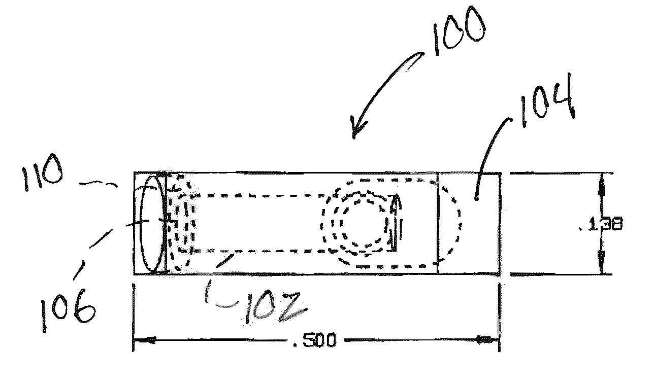
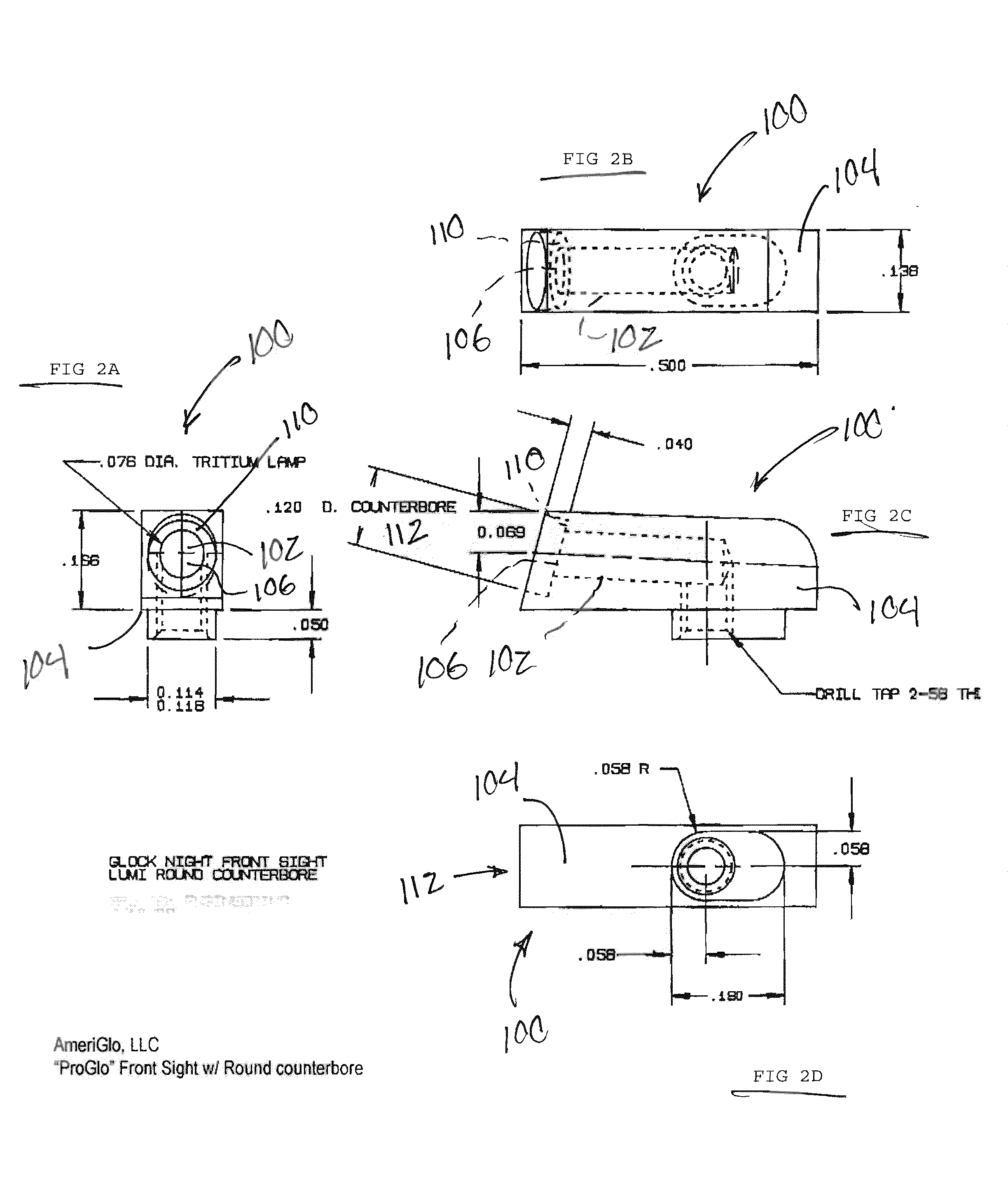
[0034]Turning now to FIGS. 2a-5, in accordance with the present invention, a first embodiment front sight is illustrated in FIGS. 2a-2d; front sight assembly 100 includes a source of illumination such as self-luminous tritium vial 102 encased in a sight housing 104 and the visible (or proximal) end of the tritium lamp 106 is surrounded with an annular surface 110 coated with non-radioactive photo-luminescent material, preferably within a counterbore such as circular counterbore 112, defined in the front sight assembly's proximal surface.

second embodiment

[0035]A second embodiment is illustrated in FIGS. 3a-3d, wherein front sight assembly 200 includes a source of illumination such as self-luminous tritium vial 102 encased in a sight housing 204 and the visible or proximal end of the tritium lamp 106 is surrounded with a square-shaped surface 210 coated with non-radioactive photo-luminescent material, preferably within a counterbore such as square counterbore 212, defined in the front sight assembly's proximal surface.

[0036]The tritium lamp feature of sight assembly 100 or 200 will provide a constant, substantially perpetual self powered ‘glow’, that is visible in low light environments while the surrounding brightly colored photo-luminescent material-covered surface (110 or 210) will be highly visible in daylight and, after storing energy from a secondary source, highly visible in low-light environments.

[0037]The photo-luminescent material surrounding the tritium can be seen to the user whether it is ‘charged’ or not charged, based ...


PUM


Abstract

A front sight assembly includes a self powered substantially permanent light source such as tritium source carried within a bore defined in a housing, where the housing preferably defines a structure symmetrically aligned along a central plane, where the bore carrying the light source has a central axis that lies within or parallel to the housing's central plane. The sight assembly housing terminates proximally in a proximal surface that faces the user when mounted on a firearm or other instrument. The sight assembly housing's proximal surface further includes a region surrounding or defining a periphery around the light source which is coated with, laminated with or altered to define a region of photo-luminescence that is substantially concentric with the center of the visible portion of light source.

Description

PRIORITY CLAIMS AND REFERENCE TO RELATED APPLICATIONS [0001]This application claims priority to related and commonly owned U.S. provisional patent application No. 61 / 136,776, filed Oct. 2, 2008, the entire disclosure of which is incorporated herein by reference.BACKGROUND OF THE INVENTION [0002]1. Field of the Invention[0003]The present invention relates to sights and, more particularly, to sights adapted for use in low-light environments on firearms and other instruments.[0004]2. Discussion of the Prior Art[0005]For purposes of nomenclature and as an example of one type of firearm, FIG. 1 illustrates a Glock model 17 pistol. When using or shooting a pistol, the user grasps grip frame and aims by aligning a notch or aperture included as part of a rear sight with the distal front sight, thereby pointing the pistol's muzzle at a target. The front sight is usually an upwardly projecting protuberance mounted at or near the muzzle or distal end of the pistol's barrel or slide. An importa...

Claims


Application Information

Patent Timeline
IPC IPC(8): F41G1/00F41G1/32F41G1/02
CPCF41G1/32F41G1/01
Inventor CALLIHAN, RICK
Owner CALLIHAN RICK
Why Eureka
Try Eureka