Vehicle air conditioning improvement

a technology for air conditioning and vehicles, applied in the field of vehicle air conditioning improvement, can solve the problems of affecting the comfort of passengers, etc., and achieves the effects of less power, extended battery usage, and improved efficiency

Inactive Publication Date: 2010-04-15
SUNDHAR SHAAM P +2
View PDF4 Cites 36 Cited by
  • Summary
  • Abstract
  • Description
  • Claims
  • Application Information

AI Technical Summary

Benefits of technology

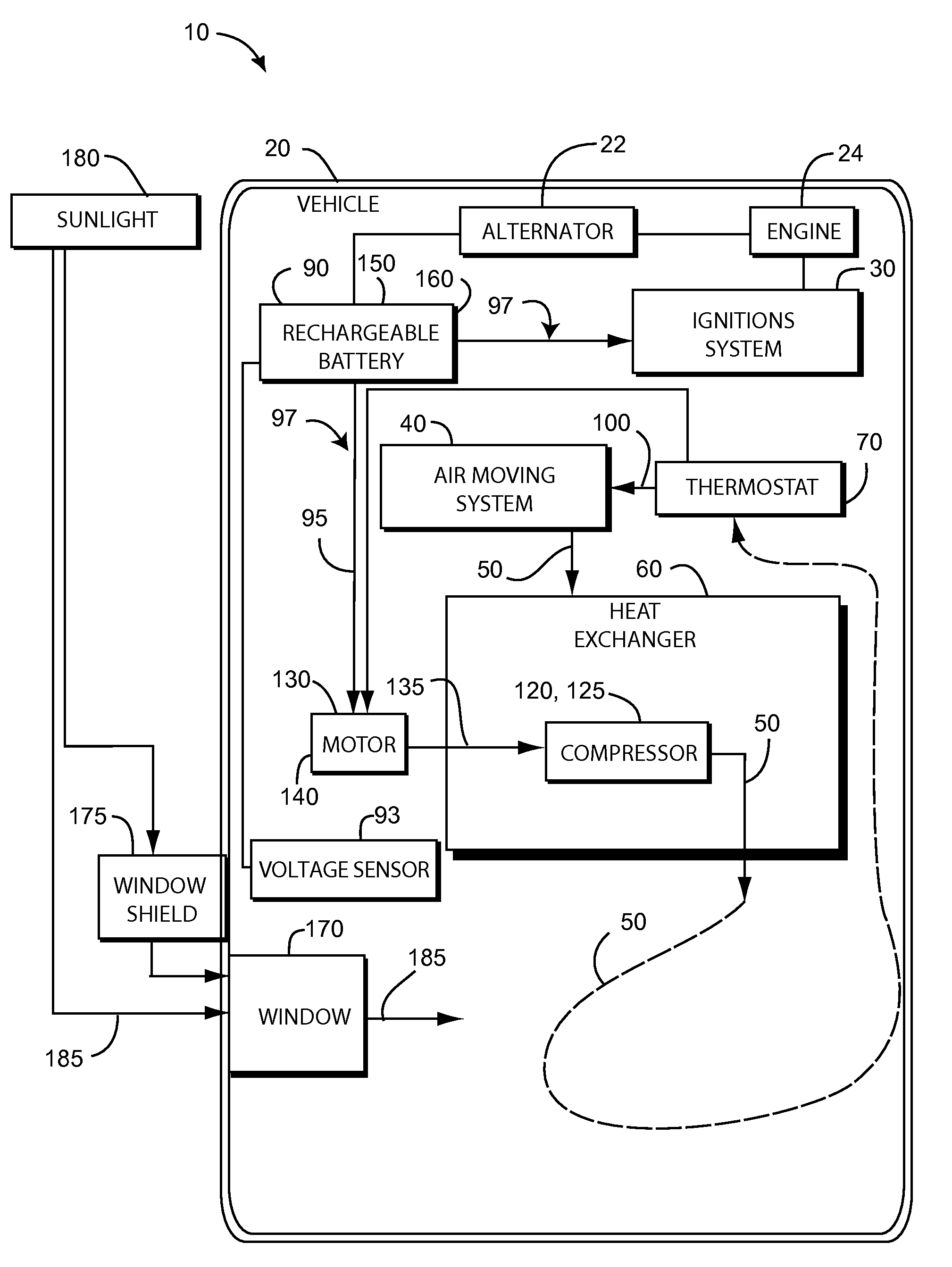
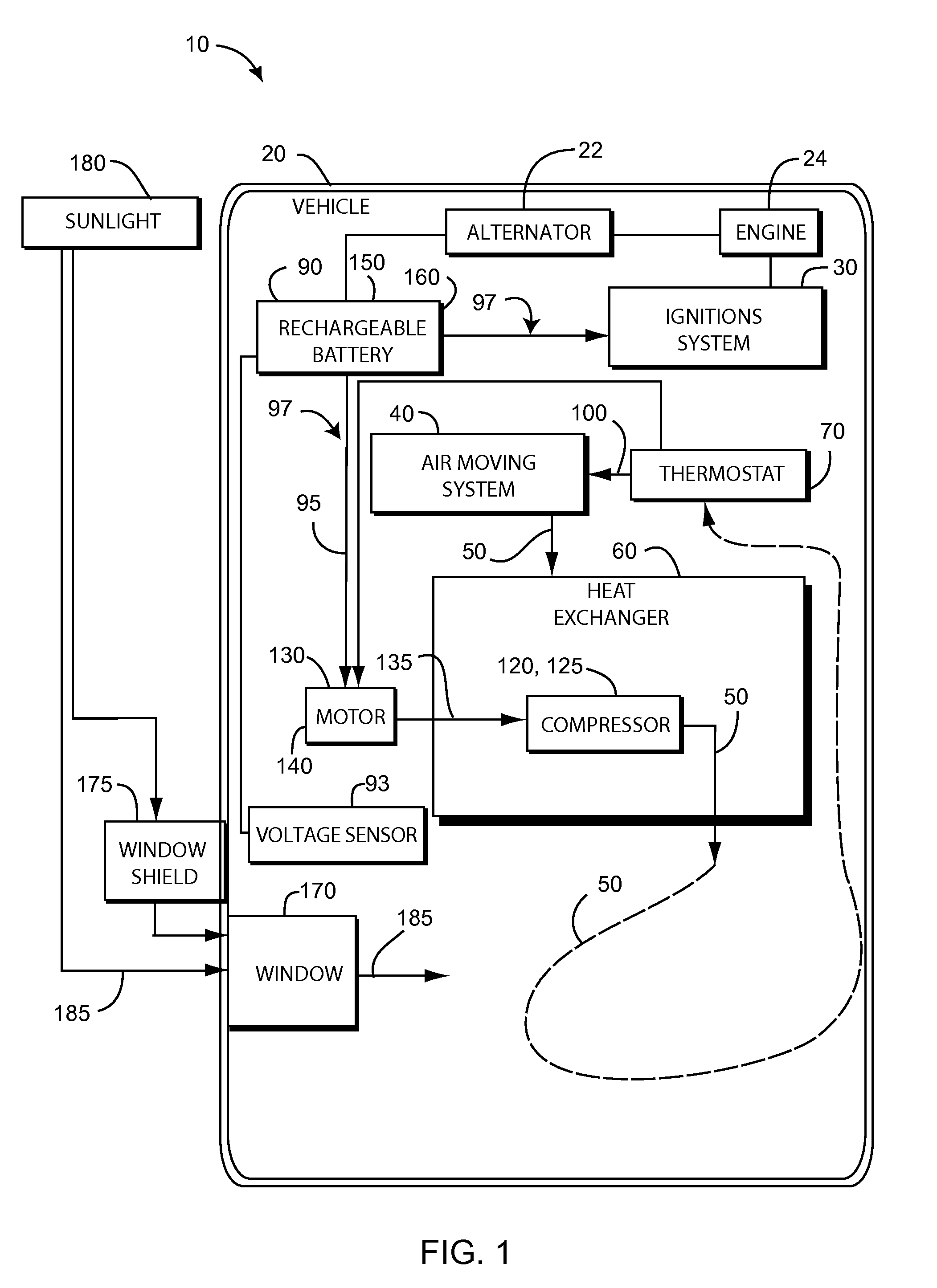
[0015]The present invention is a temperature regulation system that can be operated when the ignition system is on or off. Further, the invention is a system that can maintain desired temperature ranges in both hot weather and cold weather conditions. Also, the device provides the advantage of using the vehicles existing duct and ventilation system. In addition in hot weather, the fan of the air conditioning can be operate

Problems solved by technology

One of the most unpleasant experiences an automobilist has to endure is to return to his vehicle parked outside on a hot sunny day, and find the temperature inside quite unbearable and suffocating.
Currently these methods are used to decrease the interior temperature to some extent but not to a comfortable level, not even to the outside ambient temperature when the weather is hot.
However, the aforementioned attempts are cumbersome to use and inefficient.
Also, the air conditioner can only function if the vehicle's ignition system is in operation.
Attempts

Method used


Image

  • Vehicle air conditioning improvement
  • Vehicle air conditioning improvement
  • Vehicle air conditioning improvement

Examples


Embodiment Construction

[0020]Illustrative embodiments of the invention are described below. The following explanation provides specific details for a thorough understanding of and enabling description for these embodiments. One skilled in the art will understand that the invention may be practiced without such details. In other instances, well-known structures and functions have not been shown or described in detail to avoid unnecessarily obscuring the description of the embodiments.

[0021]Unless the context clearly requires otherwise, throughout the description and the claims, the words “comprise,”“comprising,” and the like are to be construed in an inclusive sense as opposed to an exclusive or exhaustive sense; that is to say, in the sense of “including, but not limited to.” Words using the singular or plural number also include the plural or singular number respectively. Additionally, the words “herein,”“above,”“below” and words of similar import, when used in this application, shall refer to this appli...


PUM


Abstract

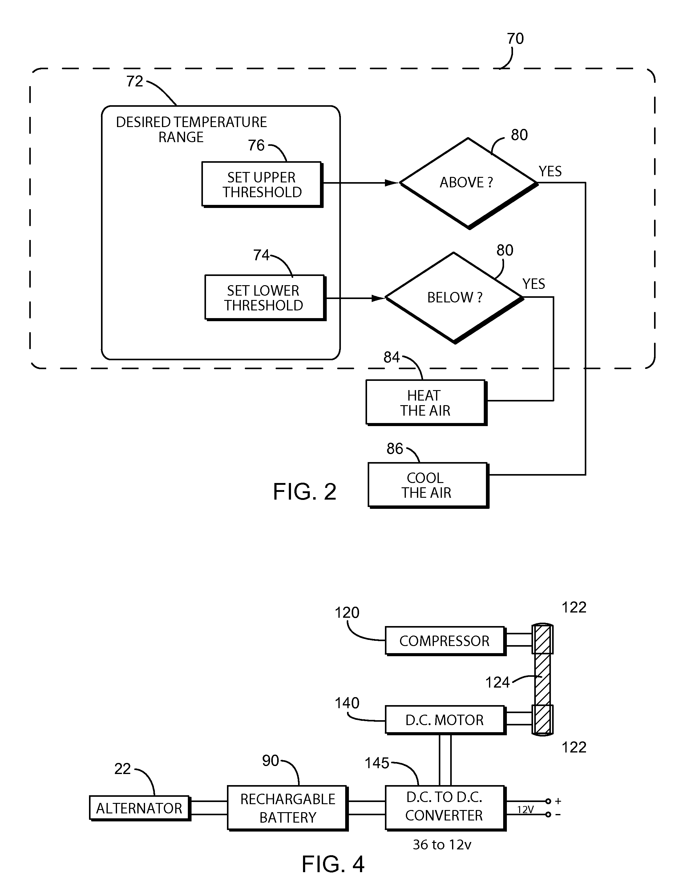
The present device is a temperature regulation system for a vehicle turned on or off. The temperature regulation system includes a rechargeable battery for supplying power to an air moving system and a heat exchanger in accordance with demand signals from the thermostat, independent of the on/off state of the ignition system. In one embodiment, a DC motor is electrically connected to the rechargeable battery and rotationally coupled to a variable-speed compressor replacing the existing compressor of the vehicle, improving efficiency and extending the use of the rechargeable battery. The temperature regulation system may be used to heat or to cool the vehicle when the temperature of the air in the vehicle exceeds a certain threshold.

Description

CROSS-REFERENCE TO RELATED APPLICATIONS[0001]This application claims the benefit of U.S. Provisional Patent Application 61 / 196,121, filed on Oct. 15, 2008, and incorporated herein by reference.STATEMENT REGARDING FEDERALLY SPONSORED RESEARCH AND DEVELOPMENT[0002]Not Applicable.FIELD OF THE INVENTION[0003]This invention relates to environmental heating and cooling systems, and more particularly to an improved such system for a vehicle.DISCUSSION OF RELATED ART[0004]One of the most unpleasant experiences an automobilist has to endure is to return to his vehicle parked outside on a hot sunny day, and find the temperature inside quite unbearable and suffocating. The same is the case in winter, in which case the temperature dips to the other extreme once the heater is switched off, and vehicle locked.[0005]Some of the methods employed at present to solve the abovementioned issues are to roll down the windows slightly, and using window shields or blinds to decrease exposure of the vehicle...

Claims


Application Information

Patent Timeline
IPC IPC(8): B60H1/00
CPCB60H1/00428B60H2001/3292B60H1/3222Y02T10/88
Inventor SUNDHAR, SHAAM P.LEE, HENG SOONSANKHLA, RAHUL
Owner SUNDHAR SHAAM P
Why Eureka
Try Eureka