High-speed actuator for valves

a high-speed actuator and actuator technology, applied in the direction of liquid transfer devices, instruments, liquid handling, etc., can solve the problems of inability to quickly and precisely control the discharge valve, and the difficulty of accurately dispensed powdered bulk materials, so as to improve the accuracy of dispensing and high-speed discharge valve positioning

Active Publication Date: 2010-04-15
BRANDT JR ROBERT O
View PDF9 Cites 4 Cited by
  • Summary
  • Abstract
  • Description
  • Claims
  • Application Information

AI Technical Summary

Benefits of technology

[0005]The present invention provides an improved high-speed actuator that allows for highly accurate discharge valve positioning, while at the same time breaks up clumped powder type material as it passes the dispenser's discharge valve and exits the dispenser's discharge conduit. In particular, the present invention improves the accuracy of dispensing bulk materials such as powders from a bulk materials hopper, by precisely controlling the percentage of openness between the discharge valve's fully open and fully closed positions. Moreover, the present invention includes a means to urge the breakup of clumped powder material, while at the same time maintaining the precise control of the discharge valve's position. For the purpose of this disclosure, a valve is a device that regulates the flow of substances (e.g., gases, fluidized solids, slurries, or liquids) by opening, closing, or partially obstructing various passageways. A valve typically includes a valve stopper and a valve seat.
[0008]A linear variable differential transformer (LVDT) magnetically coupled to the second solenoid armature is included to determine the instantaneous position of the valve stopper relative to the valve's seat. The LVDT is responsive to the position of the second armature, and generates an instantaneous valve position signal as the rod, valve stopper and second armature all move in concert with the first armature. It is important to note that electromechanical variable resistors or potentiometers having a wiper attached to the rod would only be considered for position feedback in low-speed, low-repetition actuator applications due to a relatively high production of mechanical friction. In contrast, an LVDT is very durable in high-speed, high repetition actuator applications due to its lack of contact between its moving armature and measuring coils, which results in relatively friction-free operation.
[0009]Another important advantage to using an LVDT for position feedback with the present invention is its infinite resolution capability that is limited only by the noise in an LVDT signal. As a result, an LVDT has superior position-measuring repeatability.
[0012]In a preferred embodiment, the control means further includes a proportional-differential-integral (PID) compensator to scale and compensate the valve position signal to maximize the response of the controller such that the instantaneous valve position matches the desired valve position in the least amount of time. The proportional or P element of the PID makes a change to the valve position error that is proportional to the current error value. The integral or I element is proportional to both the magnitude of the error and the duration of the error, while the differential or D element is used to reduce the magnitude of the overshoot produced by the integral or I element.

Problems solved by technology

Powdered bulk materials such as these are very difficult to dispense accurately.
One problem is that hopper type dispensers have a discharge valve that up until now cannot be rapidly and precisely controlled between fully open and fully closed positions.
Moreover, powdered type bulk materials tend to clump together as they pass the discharge valve and into a discharge conduit.

Method used


Image

  • High-speed actuator for valves
  • High-speed actuator for valves
  • High-speed actuator for valves

Examples


Embodiment Construction

[0020]In the following description, terms such as horizontal, upright, vertical, above, below, beneath, and the like, are used solely for the purpose of clarity in illustrating the invention, and should not be taken as words of limitation. The drawings are for the purpose of illustrating the invention and are not intended to be to scale.

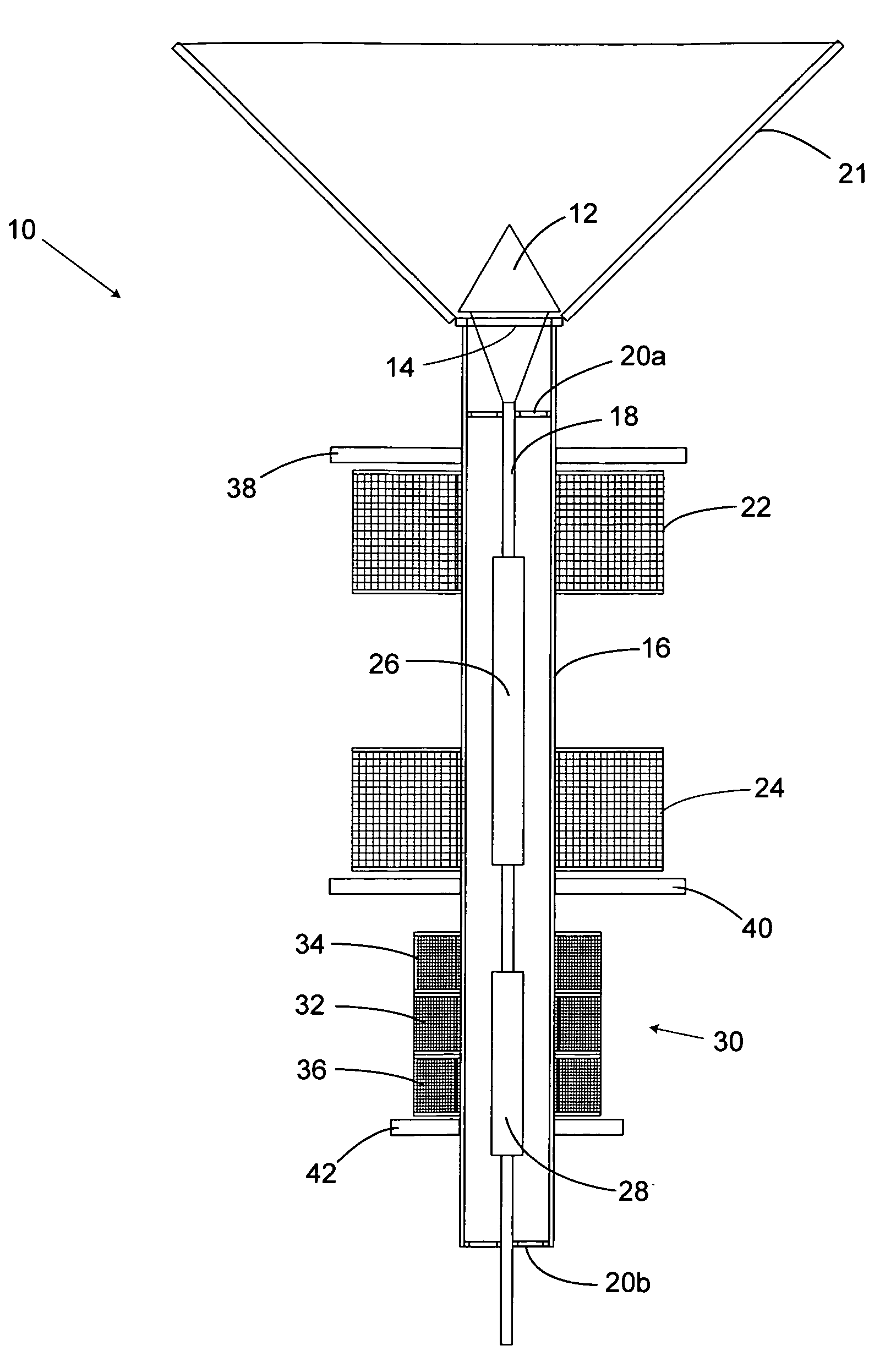
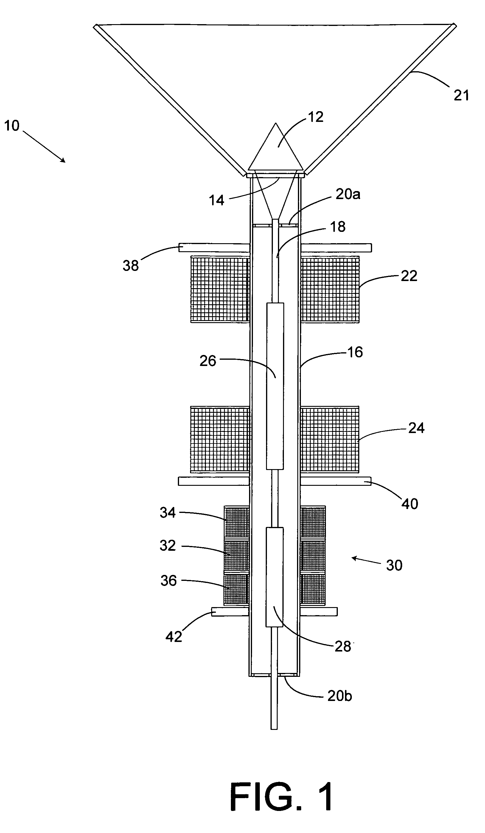
[0021]FIG. 1 depicts one embodiment of the present invention, which is a high-speed actuator, generally 10. Actuator 10 includes a discharge valve stopper 12 that has a closed position against a valve seat 14 and an open position extended away from valve seat 14. The stroke of the valve is selected such that material flow past valve stopper 12 is maximized when valve stopper 12 is in its open position. For the purposes of this disclosure the fully open position is considered to have an openness value of 100% and the fully closed position is considered to have an openness value of 0%.

[0022]As shown in FIG. 1, high-speed actuator 10 also includes a dis...


PUM


Abstract

A high-speed actuator to move a valve stopper to a closed position against a valve seat and an open position away from the valve seat is disclosed. The actuator includes a rod carrying first and second axially spaced solenoid armatures. The rod also has a valve stopper connector end. A first solenoid coil surrounds and is spaced from the rod to bias the first solenoid armature along with the rod and valve stopper toward the valve's open position. A second solenoid surrounds and is spaced from the rod. The second solenoid is axially spaced from the first solenoid to bias the first armature towards the valve's closed position. A linear variable differential transformer (LVDT) magnetically coupled to the second solenoid armature is included to determine the instantaneous position of the valve stopper relative to the valve's seat. The LVDT is responsive to the position of the second armature. The LVDT generates an instantaneous valve position signal in concert with the movements of the rod. A valve position control circuit is adapted to receive a valve position set point from a user's input, and a valve position feedback signal from the LVDT. The valve position control circuit includes first and second solenoid coil drive signals that urge the first armature, and hence the valve stopper to the valve position set point inputted by a user. A signal generator circuit is provided to vibrate the valve about a position set point in order to enhance material discharge down the discharge tube.

Description

BACKGROUND OF THE INVENTION [0001](1) Field of the Invention[0002]The present invention relates to a high-speed actuator usable to precisely control a valve for dispensing bulk materials. In particular, the present invention is particularly well suited for rapidly controlling the position of valve stoppers used to dispense bulk materials such as powders from a gravity-feed bulk materials hopper.[0003](2) Description of the Prior Art[0004]Bulk material dispensers are used to dispense powdered materials such as coffee, tea, sugar and the like. Powdered bulk materials such as these are very difficult to dispense accurately. One problem is that hopper type dispensers have a discharge valve that up until now cannot be rapidly and precisely controlled between fully open and fully closed positions. Moreover, powdered type bulk materials tend to clump together as they pass the discharge valve and into a discharge conduit. What is needed is a high-speed actuator usable to rapidly and precise...

Claims


Application Information

Patent Timeline
Patent Type & Authority Applications(United States)
IPC IPC(8): F16K31/02
CPCF16K37/0041F16K31/0679
Inventor BRANDT, JR., ROBERT O.
Owner BRANDT JR ROBERT O
Why Eureka
Try Eureka