Method of performing MRI with an atomic magnetometer

a magnetometer and atomic magnetometer technology, applied in the field of magnetic resonance imaging (mri), can solve the problems of high risk factors, death and injury, and exam can take a very long time,

Active Publication Date: 2010-04-15
TRIAD NAT SECURITY LLC
View PDF26 Cites 38 Cited by
  • Summary
  • Abstract
  • Description
  • Claims
  • Application Information

AI Technical Summary

Problems solved by technology

However, MRI has traditionally been performed in very strong magnetic field (typically >1 T) and this presents a number of risk factors during use.
MRI is also not recommended in emergency situations, because life-support equipment cannot safely enter the scanner area and the exam can take a very long time.
Instances of deaths and injuries have occurred due to movement of objects by the fields created by the magnets of conventional MRI devices.
While the risk is greatest in the case of implanted devices, there is also risk from any loose metal object

Method used


Image

  • Method of performing MRI with an atomic magnetometer
  • Method of performing MRI with an atomic magnetometer
  • Method of performing MRI with an atomic magnetometer

Examples


Embodiment Construction

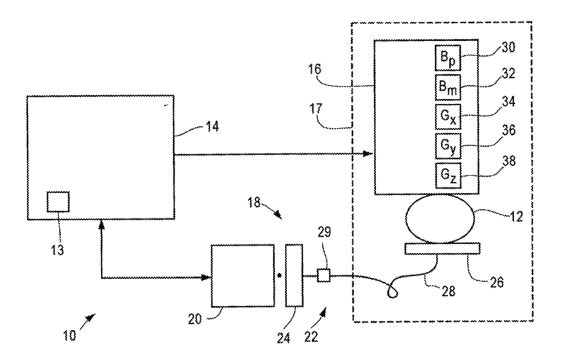
[0013]FIG. 1 is a block diagram of a MRI system 10 shown generally in accordance with an illustrated embodiment of the invention. The system 10 may be used to form two or three dimensional image of object 12. The object 12 may be a person, an animal or inanimate objects.

[0014]The system 10 is a non-cryogenic ultra-low-field (ULF) magnetic resonance imaging (MRI) system based on the use of an atomic magnetometer (AM). The system 10 is useful for general biomedical imaging. Ultra-low-field means a magnetic field in the microtesla range. ULF MRI can supplement conventional MRI scanners (i.e. those operating at magnetic fields >1 Tesla) in various applications where high fields are limiting factors. ULF-MRI systems have numerous advantages such as compatibility with magnetoencephalography (MEG), simplified magnetic field generation and field homogeneity requirements, narrow NMR linewidths, decreased susceptibility artifacts, variable field measurements, and the possibility of enhanced t...


PUM


Abstract

A method and apparatus are provided for performing an in-situ magnetic resonance imaging of an object. The method includes the steps of providing an atomic magnetometer, coupling a magnetic field generated by magnetically resonating samples of the object through a flux transformer to the atomic magnetometer and measuring a magnetic resonance of the atomic magnetometer.

Description

FIELD OF THE INVENTION[0001]The field of the invention relates to magnetic resonant imaging (MRI) and more particularly to the use of an atomic magnetometer for performing MRI.BACKGROUND OF THE INVENTION[0002]Magnetic resonance imaging is a very important diagnostic tool for modern medicine. It is non-invasive, does not involve ionizing radiation (unlike the X-ray counterparts) and is sensitive to soft tissues with various contrast enhancement possibilities. However, MRI has traditionally been performed in very strong magnetic field (typically >1 T) and this presents a number of risk factors during use. For example, patients with various implanted metallic objects (e.g., cochlear implants, brain aneurysm clips, certain artificial heart valves, vascular stents, artificial joints, dental implants) cannot have MRI. MRI is also not recommended in emergency situations, because life-support equipment cannot safely enter the scanner area and the exam can take a very long time. A careful...

Claims


Application Information

Patent Timeline
IPC IPC(8): G01R33/48
CPCG01R33/26G01R33/5611G01R33/445G01R33/3621
Inventor SAVUKOV, IGOR MYKHAYLOVICHMATLASHOV, ANDREI NIKOLAEVICHESPY, MICHELLE A.VOLEGOV, PETR LVOVICHKRAUS, JR., ROBERT HENRYZOTEV, VADIM SERGEYEVICH
Owner TRIAD NAT SECURITY LLC
Why Eureka
Try Eureka