Image processing apparatus and image processing method

Inactive Publication Date: 2010-04-15
CANON KK
View PDF5 Cites 84 Cited by
  • Summary
  • Abstract
  • Description
  • Claims
  • Application Information

AI Technical Summary

Benefits of technology

[0014]The present invention has been made in consideration of the aforementioned problems, and provides a technique which can realize a si

Problems solved by technology

The magnetic sensor is vulnerable to ambient electromagnetic waves, while the gyro sensor is susceptible to a drift phenomenon in which an output voltage drifts.
In this way, it is difficult for only the three-dimensional position and orientation sensor to generate stable position and orientation information.
Also, in a video see-through HMD that has to use the same field angle since it is technically difficult to set the field angle of an optical system of the HMD to be broader than t

Method used


Image

  • Image processing apparatus and image processing method
  • Image processing apparatus and image processing method
  • Image processing apparatus and image processing method

Examples


Example

First Embodiment

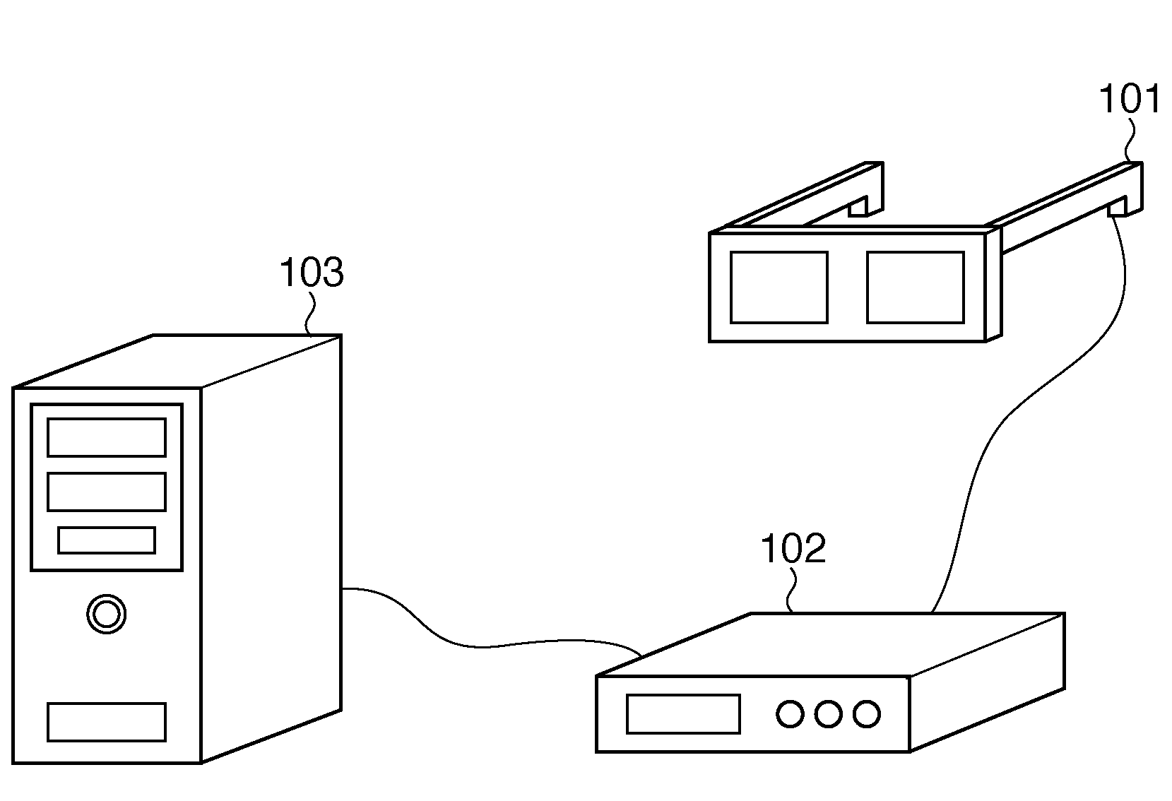
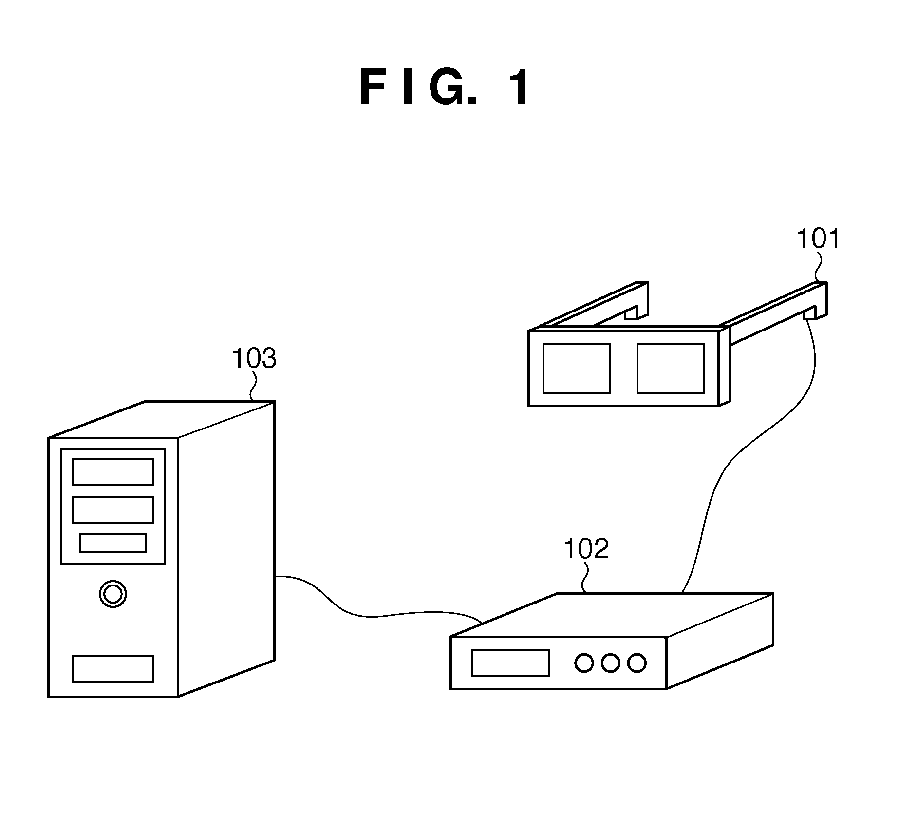
[0061]FIG. 1 is a view showing an example of the outer appearance of a system which is applicable to a system according to this embodiment. The system shown in FIG. 1 includes an HMD 101, controller 102, and image processing apparatus 103.

[0062]A mixed reality technique, that is, a so-called MR technique as a technique for seamlessly blending physical and virtual spaces in real time, uses a display apparatus with an image sensing function. In the following description, the display apparatus with an image sensing function will be referred to as an HMD. Note that this display apparatus may be a hand-held type apparatus such as binoculars and is not limited to a head-mounted apparatus. With the MR technique, a CG image, which is generated based on three-dimensional position and orientation information including the position and direction of a user's viewpoint, is superimposed on a background image of a physical space, which is acquired by an image sensing device of the ...

Example

Second Embodiment

[0128]A characteristic feature of this embodiment lies in that a time delay from image sensing until display is eliminated to enhance realtimeness. In the first embodiment, the image composition unit is included in the image processing apparatus side. However, in this embodiment, this image composition unit is included in the HMD side. As a result, a processing time required to acquire a sensed image on the image processing apparatus side is shortened.

[0129]In this embodiment, the number of indices used to generate position and orientation information is limited, and a delay caused by the processing load of convergence arithmetic operations is eliminated.

[0130]Furthermore, this embodiment also has the following characteristic feature. That is, the next image sensing position is predicted based on the motion of a sensed image on the HMD side, and an image in the predicted direction is clipped and presented, thereby hiding (virtually eliminating) a delay time required...

Example

Third Embodiment

[0195]A system according to this embodiment includes a sensing unit used to sense an image of a physical space seen from the vicinity of the right eye of the user, and a sensing unit used to sense an image of the physical space seen from the vicinity of the left eye. Note that the fields of view of the respective sensing units do not overlap each other. That is, sensed images by the respective sensing units do not redundantly include the same landscape. As a result, the field of view required to detect indices can be further broadened.

[0196]FIG. 20 is a block diagram showing an example of the functional arrangement of a system according to this embodiment. Note that the same reference numerals denote the same units as those shown in FIG. 12 in respective units shown in FIG. 20. As shown in FIG. 20, the system according to this embodiment includes an image processing apparatus 1202 and HMD 2001. That is, in the system according to this embodiment, only the HMD 2001 is...


PUM


Abstract

An index extraction unit detects indices from a sensed image sensed by a sensing unit which senses an image of a physical space on which a plurality of indices is laid out. A convergence arithmetic unit calculates position and orientation information of the sensing unit based on the detected indices. A CG rendering unit generates a virtual space image based on the position and orientation information. A sensed image clipping unit extracts, as a display image, an image in a display target region from the sensed image. An image composition unit generates a composite image by compositing the extracted display image and the generated virtual space image. A display unit displays the composite image.

Description

BACKGROUND OF THE INVENTION[0001]1. Field of the Invention[0002]The present invention relates to a technique for presenting a composite image of a sensed image and virtual space image to the user.[0003]2. Description of the Related Art[0004]In recent years, as a technique for seamlessly blending physical and virtual worlds in real time, a so-called MR (Mixed Reality) technique is known. As one MR technique, the following technique is known. That is, an image of an object which nearly matches an object observed from the pupil position of an observer is sensed using a video camera or the like equipped on a video see-through HMD (Head Mounted Display). An image obtained by superimposing a CG (Computer Graphics) on that sensed image is presented to the observer.[0005]The video see-through HMD acquires digital image data of an object by sensing an image of that object using a charge coupled device such as a CCD, and displays an MR image (mixed reality image) obtained by superimposing a C...

Claims


Application Information

Patent Timeline
IPC IPC(8): H04N13/04G09G5/00
CPCG06F3/011G06T7/0042H04N13/0278G06T2207/30204G06T19/006G06T7/73H04N13/279G09G5/377G09G2320/0626G09G2340/12
Inventor OIKAWA, MAKOTOTSUJIMOTO, TAKUYA
Owner CANON KK
Why Eureka
Try Eureka