Light Guide Plate and Backlight Module using the same

a technology of light guide plate and backlight module, which is applied in the direction of lighting and heating apparatus, instruments, mechanical apparatus, etc., can solve the problems of difficult control of the light emitting angle of light rays, and achieve the effect of improving the brightness of the plane light source provided by the backlight module of the present invention, high light emission efficiency, and high light utilization efficiency

Active Publication Date: 2010-04-15
AU OPTRONICS CORP
View PDF4 Cites 19 Cited by
  • Summary
  • Abstract
  • Description
  • Claims
  • Application Information

AI Technical Summary

Benefits of technology

[0025]In the present invention, the light emitting angles of the light rays can be regulated by adjusting the curvature radiuses of the first curved line and the second curved line. Therefore, the light guide plate has relatively high light emitting

Problems solved by technology

In addition, the sandblasted structures 125 would make it dif

Method used


Image

  • Light Guide Plate and Backlight Module using the same
  • Light Guide Plate and Backlight Module using the same
  • Light Guide Plate and Backlight Module using the same

Examples


Embodiment Construction

[0037]Reference will now be made to the drawings to describe various exemplary embodiments of the present light guide plate and backlight module using the light guide plate in detail.

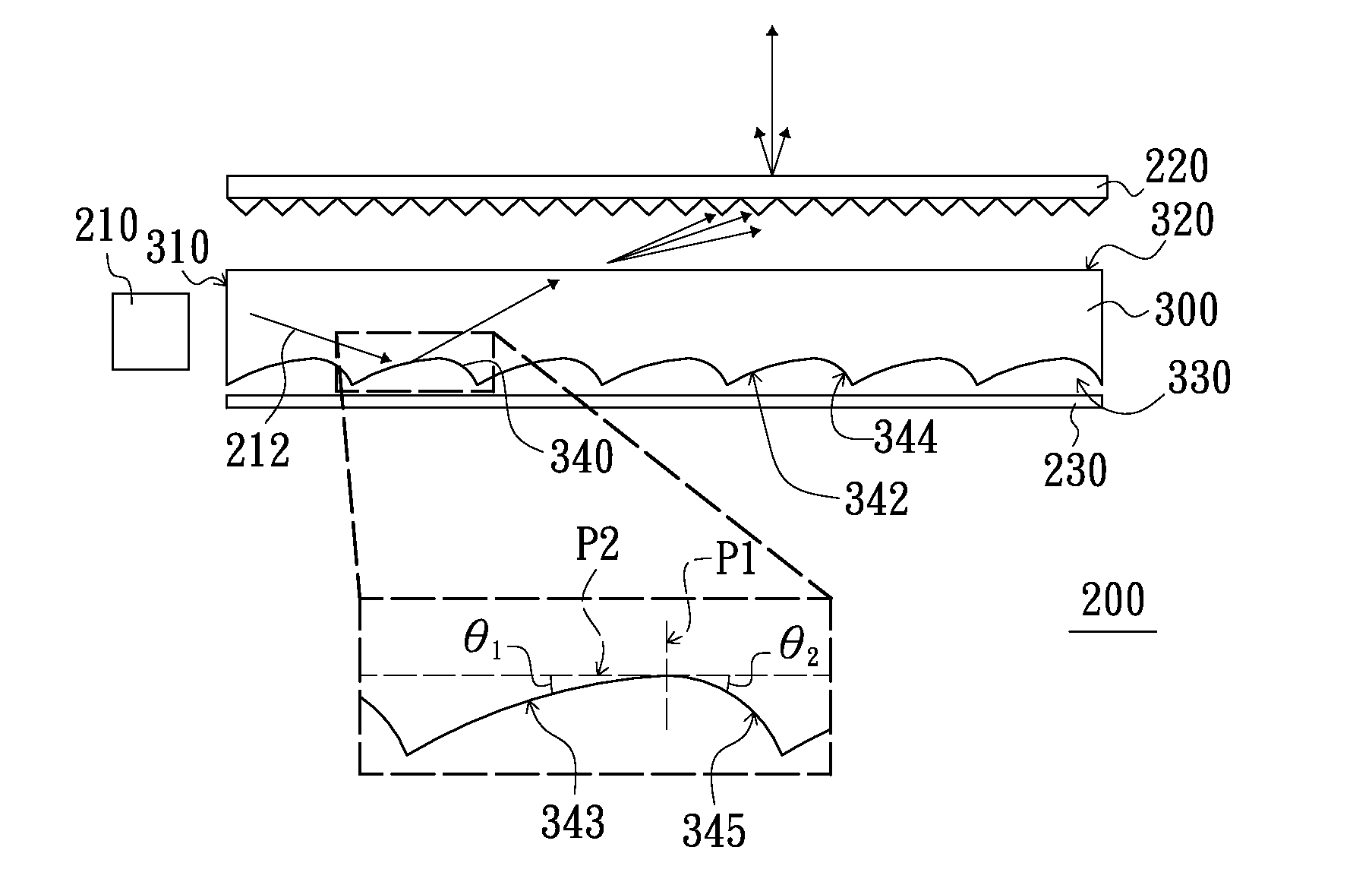
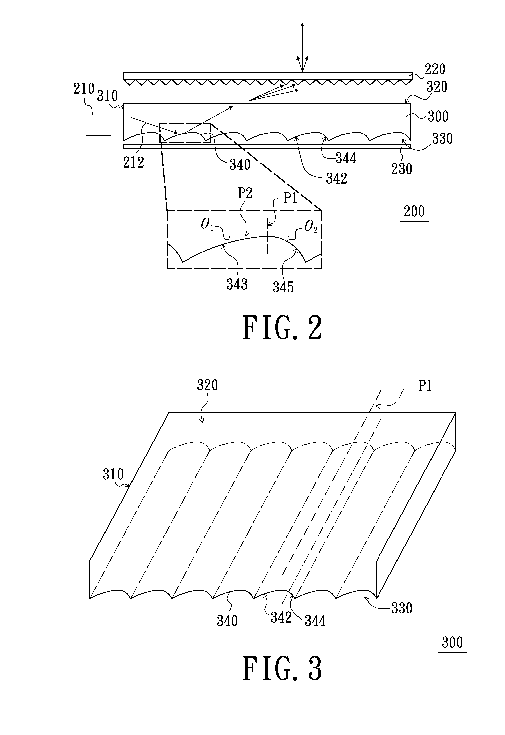
[0038]FIG. 2 is a schematic cross-sectional view of a backlight module according to an embodiment of the present invention. FIG. 3 is a schematic three-dimensional view showing a light guide plate of FIG. 2. Referring to FIGS. 2 and 3, the backlight module 200 of the present embodiment includes a light source 210, an optical sheet 220 and a light guide plate 300. The light guide plate 300 has a light incident surface 310, a light emitting surface 320 and a bottom surface 330. The bottom surface 330 is opposite to the light emitting surface 320. The light incident surface 310 is connected between the light emitting surface 320 and the bottom surface 330. The light source 210 is disposed adjacent to the light incident surface 310. The optical sheet 220 is disposed above the light emitting surface 320. The...


PUM


Abstract

A light guide plate has a light incident surface, a light emitting surface and a bottom surface. The bottom surface or the light emitting surface has a plurality of light guide units disposed thereon. Each of the light guide units has a first curved surface and a second curved surface connected with the first curved surface. Both of the first curved surface and the second curved surface are concave surfaces or convex surfaces. In a cross section perpendicular to the light incident surface and passing through the first curved surface and the second curved surface, the first curved surface and the cross section intersect in a first curved line, and the second curved surface and the cross section intersect in a second curved line. A curvature radius of the first curved line is greater than that of the second curved line.

Description

BACKGROUND[0001]1. Field of the Invention[0002]The present invention relates to a plane light source device, and more particularly to a backlight module and a light guide plate used in the backlight module.[0003]2. Description of the Related Art[0004]With the development of flat panel display technique, flat panel displays (FPDs) that have advantages of light in weight, small in size and low power consumption are becoming more and more popular. Typically, the flat panel displays include liquid crystal displays (LCDs), plasma panel displays (PDPs), organic light emitting diode displays (OLED displays) and electrophoretic displays (EPDs). Among the flat panel displays, the liquid crystal displays are most widely used.[0005]The liquid crystal display includes a liquid crystal display panel and a backlight module. The backlight module is used to provide a plane light source to the liquid crystal display panel. Generally, the backlight module may be classified into a direct type backligh...

Claims


Application Information

Patent Timeline
IPC IPC(8): F21V8/00
CPCG02B6/0038G02B6/0036
Inventor LIAO, SUPER
Owner AU OPTRONICS CORP
Why Eureka
Try Eureka