Satellite Signal Reception Device, Timekeeping Device, and Satellite Signal Reception Method

a satellite signal and reception device technology, applied in instruments, horology, wave based measurement systems, etc., can solve the problem that the positioning calculation can take a long time to converge, and achieve the effect of reducing current consumption

Active Publication Date: 2010-04-15
SEIKO EPSON CORP
View PDF15 Cites 10 Cited by
  • Summary
  • Abstract
  • Description
  • Claims
  • Application Information

AI Technical Summary

Benefits of technology

[0037]This aspect of the invention acquires the precise orbit information required to generate the positioning information, and suspends at least a part of the reception operation process during the period in which the coarse orbit information that is not needed to generate the positioning information is transmitted. As a result, a satellite signal reception method that reduces current consumption can be achieved.

Problems solved by technology

The time required to acquire the satellite information therefore depends upon the strength of the satellite signal, and the positioning calculation can take a long time to converge.

Method used


Image

  • Satellite Signal Reception Device, Timekeeping Device, and Satellite Signal Reception Method
  • Satellite Signal Reception Device, Timekeeping Device, and Satellite Signal Reception Method
  • Satellite Signal Reception Device, Timekeeping Device, and Satellite Signal Reception Method

Examples


embodiment 1

2-1 Embodiment 1

Configuration of a GPS Wristwatch

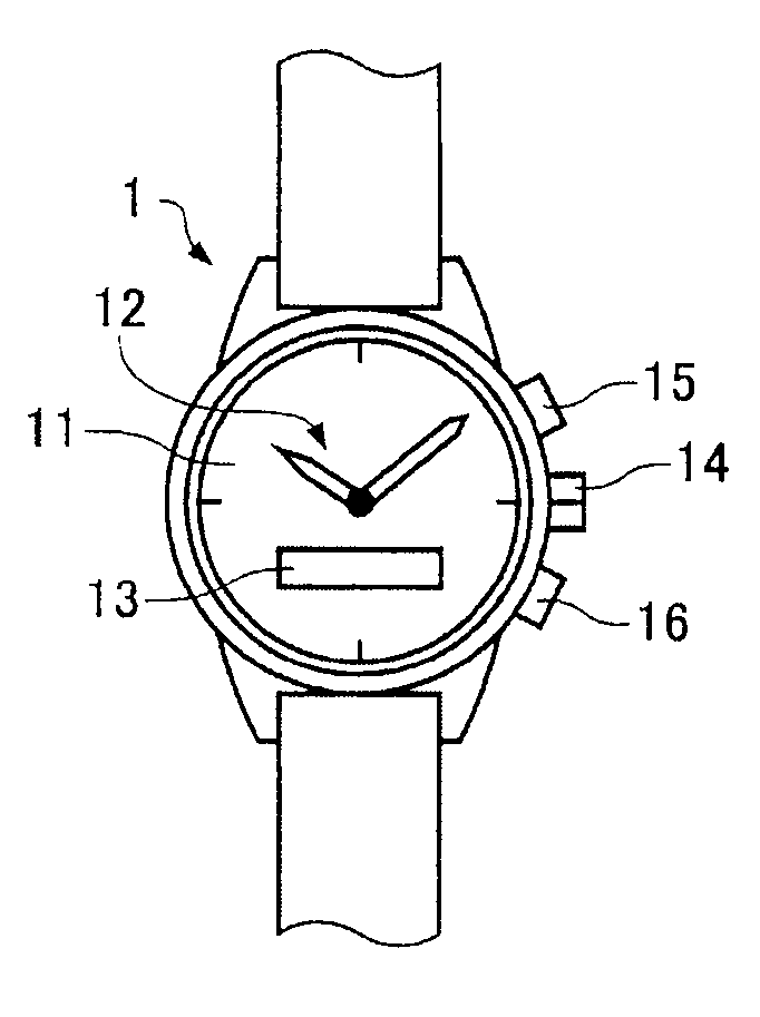
[0071]FIG. 3A and FIG. 3B are figures describing the configuration of a GPS wristwatch according to a first embodiment of the invention. FIG. 3A is a schematic plan view of a GPS wristwatch, and FIG. 3B is a schematic section view of the GPS wristwatch in FIG. 3A.

[0072]As shown in FIG. 3A, the GPS wristwatch 1 has a dial 11 and hands 12. A display 13 is disposed in a window formed in a part of the dial 11. The display 13 may be an LCD (liquid crystal display) panel, and is used to display information such as the current latitude and longitude or the name of a city in the current time zone or location, or other message information. The hands 12 include a second hand, minute hand, and hour hand, and are driven through a wheel train by means of a stepping motor.

[0073]By manually operating the crown 14 or buttons 15 and 16, the GPS wristwatch 1 can be set to a mode (“time information acquisition mode”) for receiving a satellite signal fro...

embodiment 2

2-2 Embodiment 2

[0170]The structure and circuit configuration of a GPS wristwatch according to this second embodiment of the invention are the same as the structure and circuit configuration of the GPS wristwatch according to the first embodiment of the invention shown in FIG. 3 to FIG. 6, and further description thereof is thus omitted.

[0171]Positioning Information Generating Process

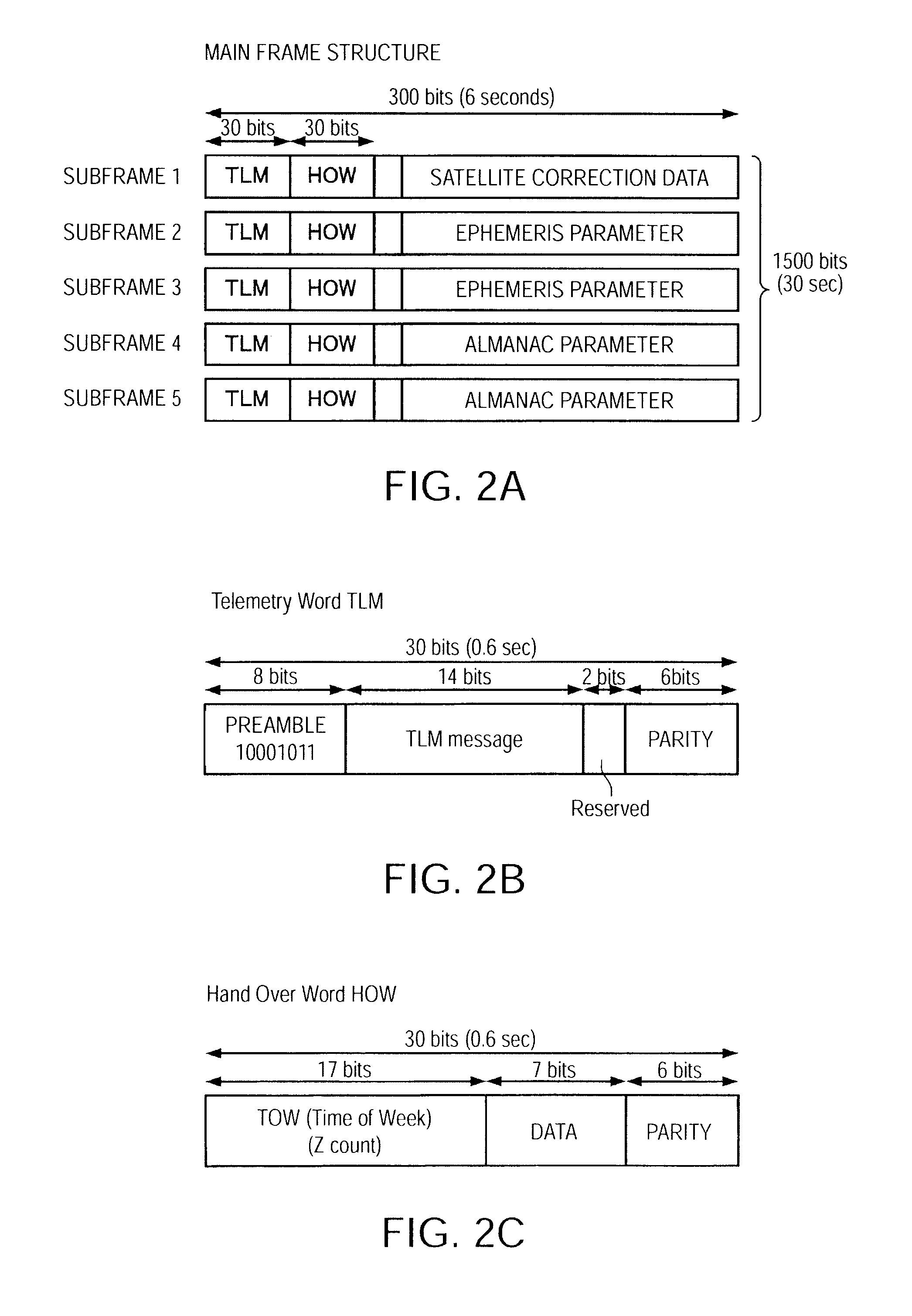
[0172]FIG. 9 is a flow chart showing an example of a positioning information generating process (positioning information acquisition mode) in a GPS wristwatch according to a second embodiment of the invention. In this second embodiment of the invention the satellite correction information period and the almanac parameter period (that is, the periods when subframes 1, 4 and 5 of the navigation message are transmitted when the positioning information satellite is a GPS satellite) are used as suspended reception periods, that is, periods in which reception is suspended. Note that identical steps in this em...

embodiment 3

2-3 Embodiment 3

[0191]The structure and circuit configuration of a GPS wristwatch according to this third embodiment of the invention are the same as the structure and circuit configuration of the GPS wristwatch according to the first embodiment of the invention shown in FIG. 3 to FIG. 6, and further description thereof is thus omitted.

[0192]Positioning Information Generating Process

[0193]FIG. 11 is a flow chart showing an example of a positioning information generating process (positioning information acquisition mode) in a GPS wristwatch according to a third embodiment of the invention.

[0194]In this third embodiment of the invention the satellite correction information period and the almanac parameter period (that is, the periods when subframes 1, 4 and 5 of the navigation message are transmitted when the positioning information satellite is a GPS satellite) are used as suspended reception periods during the time until the reception operation process is completed after the first s...


PUM


Abstract

A satellite signal reception device according to an aspect of the invention comprises a reception operation unit that executes a reception operation process to receive a satellite signal transmitted from a positioning information satellite and generates positioning information from the satellite signal. The satellite signal has precise and coarse information orbit periods containing precise and coarse orbit information respectively for the positioning information satellite. The reception operation unit executes the reception operation process in the precise orbit information period, uses the coarse orbit information period as a suspended reception period, and pauses at least a part of the reception operation process in the suspended reception period.

Description

CROSS-REFERENCE TO RELATED APPLICATION(S)[0001]Japanese Patent application No. 2008-262633 is hereby incorporated by reference in its entirety.BACKGROUND[0002]1. Field of Invention[0003]The present invention relates to a satellite signal reception device, a timekeeping device, and a satellite signal reception method.[0004]2. Description of Related Art[0005]The Global Positioning System (GPS), which is a system in which satellites (GPS satellites) orbiting the Earth on known orbits transmit signals (satellite signals) carrying superposed time information and orbit information, and a terrestrial receiver (GPS receiver) receives these signals (satellite signals) to determine its own position, is widely known.[0006]The GPS receiver captures signals from a plurality of GPS satellites, acquires satellite information including accurate time information (GPS time information) and orbit information from each of the captured satellites, performs a positioning calculation using the acquired sa...

Claims


Application Information

Patent Timeline
Patent Type & Authority Applications(United States)
IPC IPC(8): G04B47/06G01S1/00G01S19/14G01S19/34G04G5/00G04R20/02G04R60/10
CPCG01S19/24G01S19/34G04G21/04G04G5/002G01S19/35G04R20/16
Inventor FUJISAWA, TERUHIKO
Owner SEIKO EPSON CORP
Why Eureka
Try Eureka