Near- field optical head and information recording / reproducing device

a technology of optical head and information recording/reproducing device, which is applied in the direction of data recording, combination recording, instruments, etc., can solve the problems of inability to dissipate, invert or dissipate recorded information, and prone to thermal demagnetization, so as to achieve enhanced writing reliability and high quality

Inactive Publication Date: 2010-04-15
SEIKO INSTR INC
View PDF9 Cites 8 Cited by
  • Summary
  • Abstract
  • Description
  • Claims
  • Application Information

AI Technical Summary

Benefits of technology

[0051]Thereafter, the control part operates the magnetic field generating portion and the light source. Due to such an operation, the near-field optical head can record information on the magnetic recording medium using the near-field light and recording magnetic field cooperatively. Particularly, due to the provision of the above-mentioned near-field optical head, the reliability of writing can be enhanced so that the optical head can cope with high-density recording whereby the optical head can acquire high quality. Further, the information recording / reproducing device can be miniaturized simultaneously.

Problems solved by technology

When the bit size becomes small, energy which information that 1 bit possesses approximates heat energy at a room temperature and hence, there arise drawbacks of thermal demagnetization such as the inversion or the dissipation of recorded information due to thermal fluctuation or the like.
In this method, however, the dissipation of the recorded information or the like is liable to occur due to the above-mentioned thermal demagnetization.
Accordingly, also in the above-mentioned perpendicular recording method, it has been difficult to record information on this recording medium.

Method used


Image

  • Near- field optical head and information recording / reproducing device
  • Near- field optical head and information recording / reproducing device
  • Near- field optical head and information recording / reproducing device

Examples


first embodiment

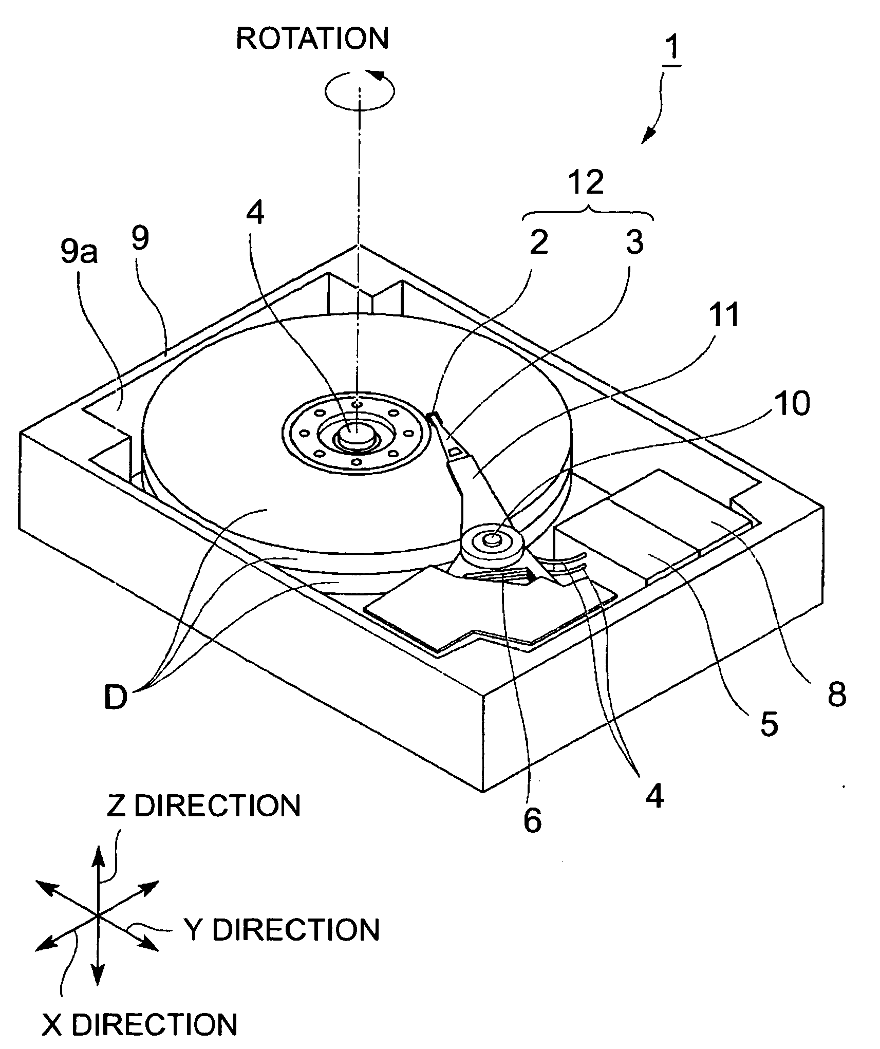
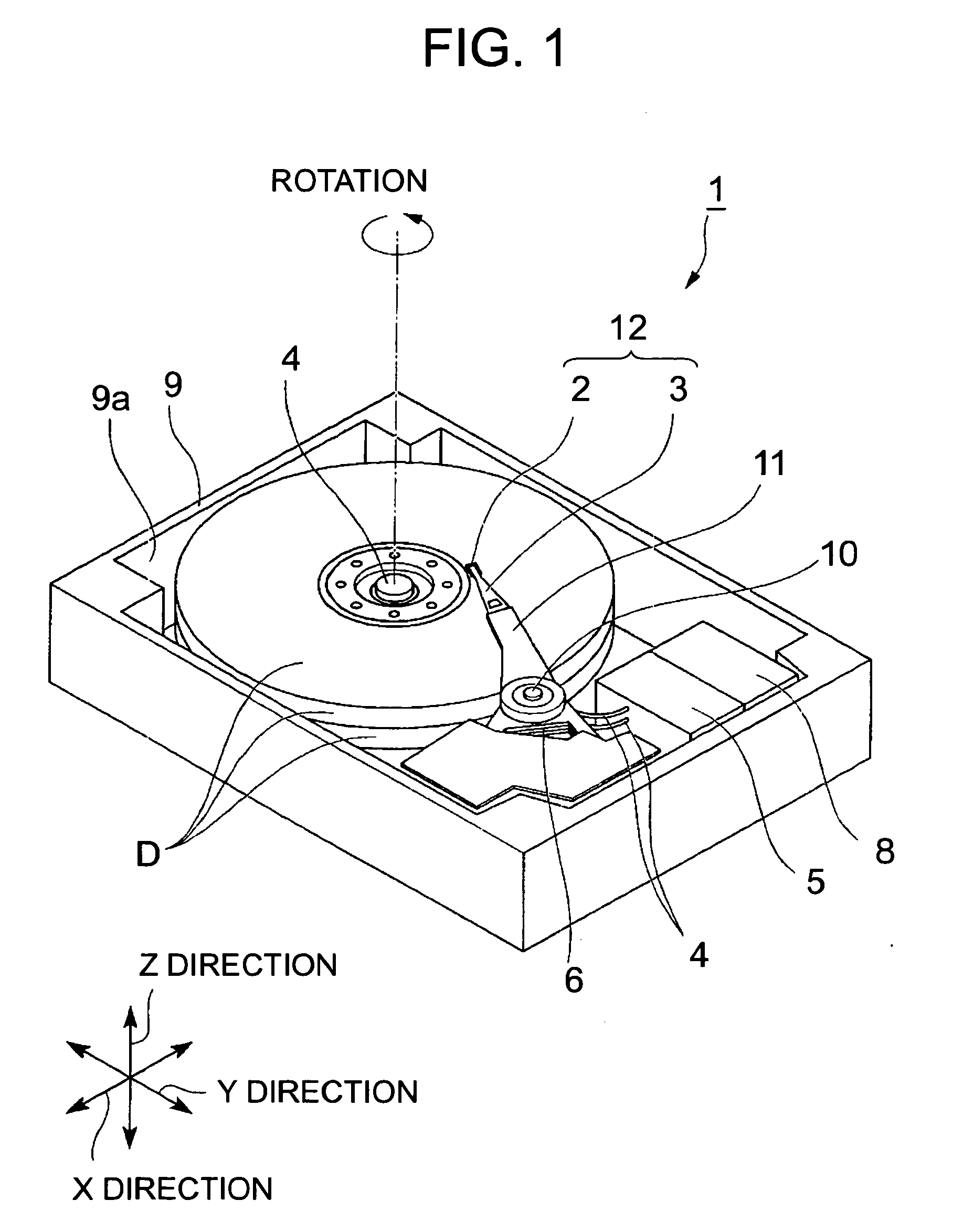
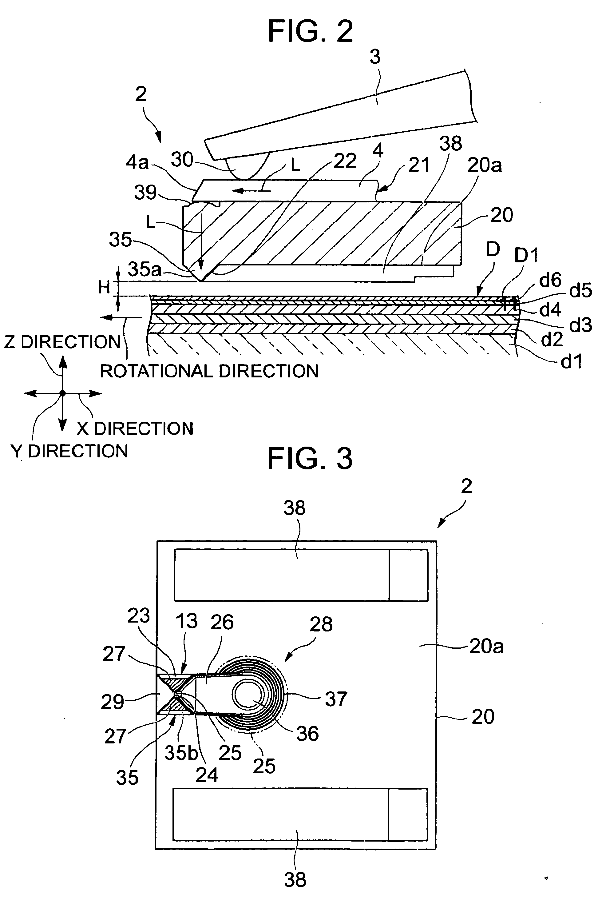
[0074]Hereinafter, a first embodiment of a near-field optical head and an information recording / reproducing device according to the present invention is explained in conjunction with FIG. 1 to FIG. 7. The information recording / reproducing device 1 of this embodiment is a device which performs writing by a perpendicular recording method with respect to a disk (magnetic recording medium) D having a perpendicular recording layer d2. This embodiment is explained by taking an air-floating-type information recording / reproducing device in which a near-field optical head 2 is floated by making use of an air flow caused by rotation of the disk D as an example.

[0075]The information recording / reproducing device 1 of this embodiment includes, as shown in FIG. 1, the near-field optical head 2, a beam 3 which is movable in the XY direction parallel to a disk surface (surface of the magnetic recording medium) D1 and supports the near-field optical head 2 on a distal end side thereof in a state whe...

second embodiment

[0119]Next, a second embodiment of the near-field optical head according to the present invention is explained in conjunction with FIG. 8 to FIG. 10. Here, in the second embodiment, constitutional parts identical to the constitutional parts of the first embodiment are given the same symbols, and their repeated explanation is omitted. The difference between the second embodiment and the first embodiment lies in a point that a main magnetic pole 24 is formed on a different surface of the polyhedron 35. Further, in FIG. 8, a metal film 27, the main magnetic pole 24 and the like are omitted from the drawing for facilitating the understanding of the drawing.

[0120]That is, in the near-field optical head 40 of this embodiment, as shown in FIG. 8 to FIG. 10, out of four side surfaces of the polyhedron 35, a side surface of polyhedron 35 which also functions as a portion of an outflow-end-side end surface of the slider 20 forms a first inclined surface 22, and the main magnetic pole 24 is fo...

third embodiment

[0123]Next, a third embodiment of the near-field optical head according to the present invention is explained in conjunction with FIG. 11 and FIG. 12. Here, in the third embodiment, constitutional parts identical to the constitutional parts of the second embodiment are given the same symbols, and their repeated explanation is omitted. The difference between the third embodiment and the second embodiment lies in a point that the position of the polyhedron 35 differs between these embodiments. Further, in FIG. 11, a metal film 27, a main magnetic pole 24 and the like are omitted from the drawing for facilitating the understanding of the drawing.

[0124]That is, in a near-field optical head 50 of this embodiment, as shown in FIG. 11 and FIG. 12, the polyhedron 35 is formed in a state where the polyhedron 35 is arranged close to one side of a slider 20. Further, corresponding to such formation of the polyhedron 35, the lens 39 and the optical waveguide 4 are also provided in a state where...


PUM

PropertyMeasurementUnit
magnetizationaaaaaaaaaa
optical fluxaaaaaaaaaa
magneticaaaaaaaaaa

Abstract

A near-field optical head includes: a slider which has an opposedly-facing surface which faces a surface of a magnetic recording medium; an optical flux introducing means which introduces the optical flux toward the opposedly-facing surface; a first inclined surface 22 and a second inclined surface 23 which project toward the magnetic recording medium from the opposedly-facing surface in an inclined manner with respect to an optical axis of the introduced optical flux, the first inclined surface and the second inclined surface being arranged adjacent to each other so as to share one side in common; a recording element 13 which is formed on one inclined surface out of both inclined surfaces and includes a main magnetic pole 24 and an auxiliary magnetic pole 26 which are stacked on each other with an insulation film 25 sandwiched therebetween; a metal film 27 which is formed on the other inclined surface out of both inclined surfaces and allows an introduced optical flux to propagate along an interface between the metal film and the other inclined surface and, thereafter, generates a near-field light R from the optical flux; and a magnetic field generating means which generates a recording magnetic field between both magnetic poles.

Description

TECHNICAL FIELD[0001]The present invention relates to a near-field optical head which can record various kinds of information with extra high density on a magnetic recording medium by a near-field light, and an information recording / reproducing device which includes the near-field optical head.BACKGROUND ART[0002]Recently, along with the increase of the capacity of a hard disk in a computer device or the like, recording density of information in a single recording surface has increased. For example, to increase the recording capacity per unit area of a magnetic disk, it is necessary to increase the surface recording density. However, along with the increase of the recording density, a recording area which 1 bit occupies on a recording medium has decreased. When the bit size becomes small, energy which information that 1 bit possesses approximates heat energy at a room temperature and hence, there arise drawbacks of thermal demagnetization such as the inversion or the dissipation of ...

Claims


Application Information

Patent Timeline
Patent Type & Authority Applications(United States)
IPC IPC(8): G11B11/00
CPCG11B5/314G11B5/6088G11B7/1387G11B2005/0021G11B11/1058G11B2005/001G11B11/10536
Inventor HIRATA, MASAKAZUOUMI, MANABUPARK, MAJUNG
Owner SEIKO INSTR INC
Why Eureka
Try Eureka