Rolling bearing

Inactive Publication Date: 2010-04-15
SCHAEFFLER TECH AG & CO KG
View PDF4 Cites 3 Cited by
  • Summary
  • Abstract
  • Description
  • Claims
  • Application Information

AI Technical Summary

Benefits of technology

[0011]According to a further advantageous feature of the invention, the guide element is configured as a sliding shoe comprising a connected radially protruding pin which engages into the recess. Advantageously, the sliding shoe is made of a sliding material, for instance, brass, so that the sliding shoe can move with low friction in the guide groove.
[0012]According to still another feature of the invention, the recess and the guide groove possess an angular range of <360°. Due to this dimension of the angular ranges, such a slewing connection can be adapted in a simple manner to the desired angle of rotation in each practical case of use.
[0014]According to still another feature of the invention, the outer bearing ring comprises on an inner peripheral surface, a projection pointing toward the inner bearing ring, which projection forms support surfaces for the angular contact thrust needle roller bearings. Due to this geometric design, the outer bearing ring can be fabricated particularly simply and thus more economically.
[0015]According to still another feature of the invention, the inner bearing ring comprises on an outer peripheral surface, a recess for receiving the angular contact thrust needle roller bearings, into which a screw ring can be screwed. This screw ring enables the setting of the desired pre-stress of such a slewing connection in a simple manner.
[0016]According to another advantageous proposition of the invention, the bearing rings are made of a light metal, for example aluminum. By this, it is assured that such a rolling bearing slewing connection, while possessing a high stability, still has a low dead weight.
[0017]According to still another feature of the invention, the thrust washers and / or the pin are subjected to a hardening treatment. In this way, the durability of the rolling bearing slewing connection is enhanced with a simultaneously increased load supporting capacity.

Problems solved by technology

A drawback of this solution is that such mechanical limiters of angles of rotation do not allow the bearing rings to rotate through an angle larger than 360°, but this is required in many cases of use.

Method used


Image

  • Rolling bearing
  • Rolling bearing
  • Rolling bearing

Examples


Embodiment Construction

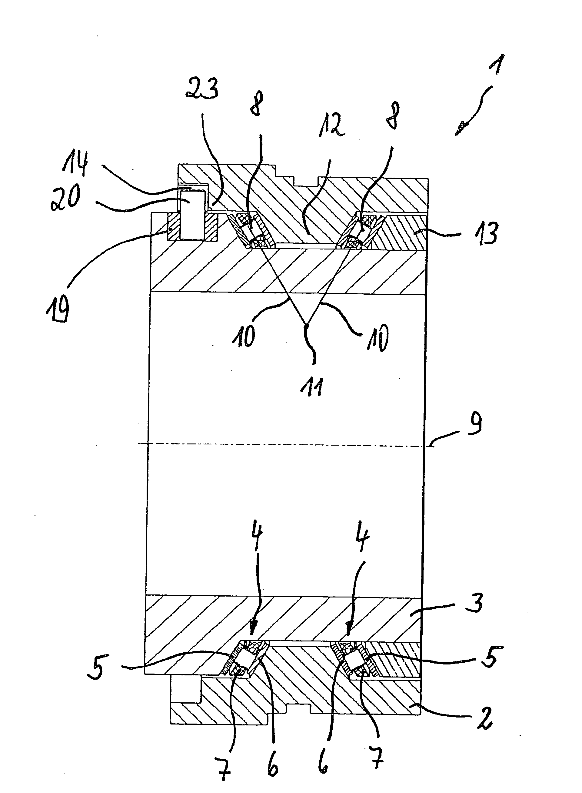
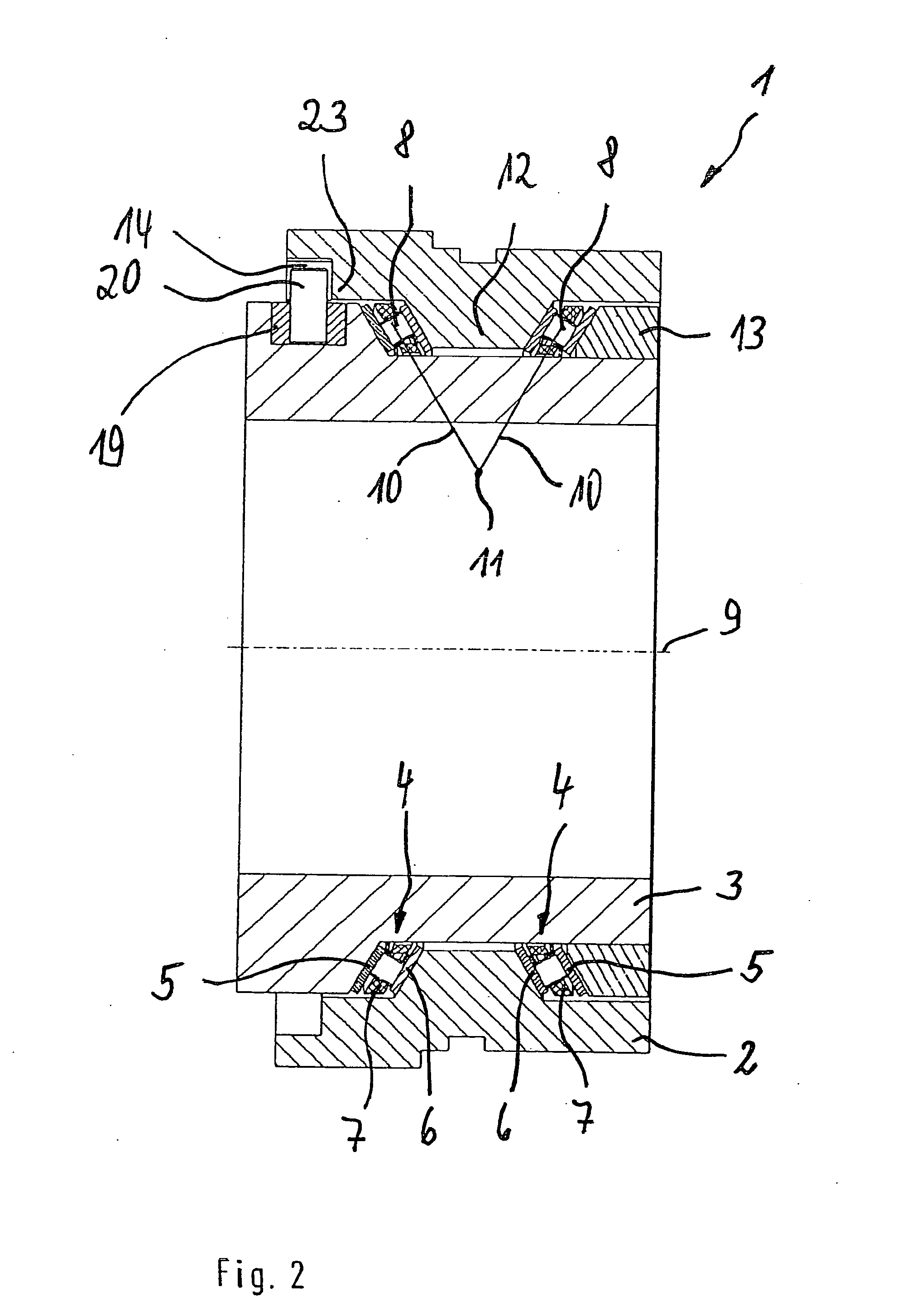
[0024]The slewing connection illustrated in FIGS. 1 and 2 and identified at 1 corresponds to the solution described in claim 1 and comprises an outer bearing ring 2 and an inner bearing ring 3 between which rings two oppositely oriented angular contact thrust needle roller bearings 4 are arranged. Each of these bearings comprises thrust washers 5, 6 between which bearing needle rollers 8 guided in respective cages 7 roll on associated raceways, not specified further. In the present example of embodiment, the angular contact thrust needle roller bearings 4 are oriented such that the prolonged axes of rotation 10 of the needle rollers 8 intersect at the point 11 within the inner bearing ring 3. The outer bearing ring 2 comprises a V-shaped projection 12 that serves as a support surface for the thrust washers 6. The slewing connection 1 further comprises a screw ring 13 that can be screwed through its inner thread, not shown, onto the inner bearing ring 3, so that the two angular conta...


PUM


Abstract

A rolling bearing, particularly a slewing connection (1), comprising an outer bearing ring (2) and an inner bearing ring (3) and rolling elements arranged between said outer and inner bearing rings for rolling contact with associated raceways, a stop means for limiting an angle of rotation of the rolling bearing being arranged within the rolling bearing, whereby a first solution offered by the invention, the outer bearing ring (2) comprises on an inner peripheral surface a recess (14) which extends in peripheral direction and is limited at two ends by a first stop lug (15), the inner bearing ring (3) comprises on an outer peripheral surface a guide groove (16) which extends in peripheral direction and is limited at two ends by a second stop lug (17), and a guide element (18) arranged in the guide groove (16) connects the inner and outer bearing rings (3,2) to each other by positive engagement.

Description

FIELD OF THE INVENTION[0001]The invention concerns a rolling bearing, particularly a slewing connection, comprising an outer bearing ring and an inner bearing ring and rolling elements arranged between said outer and inner bearing rings for rolling contact with associated raceways, a stop means for limiting an angle of rotation of the rolling bearing being arranged within the rolling bearing.BACKGROUND OF THE INVENTION[0002]Rolling bearing slewing connections of the pre-cited type are known in the prior art. The textbook “Die Wälzlagerpraxis” (Rolling bearing practice), Vereinigte Fachverlage GmbH, Mainz 1995 teaches that rolling bearing slewing connections of the pre-cited type are used as pivoting bearings for the support of excavators, cranes and in the field of automotive vehicles for articulated buses and streetcars, i.e. in fields of use in which, in a limited design space, high loads occur and where a high degree of operative safety is demanded. These slewing connections can ...

Claims


Application Information

Patent Timeline
IPC IPC(8): F16C19/24
CPCF16C11/04F16C33/60F16C19/38F16C11/10F16C19/30F16C2300/28F16C2316/10F16M11/2014F16M13/027
Inventor STOLZLE, JURGEN
Owner SCHAEFFLER TECH AG & CO KG
Why Eureka
Try Eureka