Method of making diagram for use in selection of wavelength of light for polishing endpoint detection, method and apparatus for selecting wavelength of light for polishing endpoint detection, polishing endpoint detection method, polishing endpoint detection apparatus, and polishing monitoring method

a technology of endpoint detection and diagram, which is applied in the direction of grinding machine components, manufacturing tools, lapping machines, etc., can solve the problems of difficult monitoring of the progress of the polishing process, interference of light waves from these interfaces, and photocorrosion, so as to achieve the effect of effectively selecting optimal wavelengths and optimal wavelengths of ligh

Active Publication Date: 2010-04-15
EBARA CORP
View PDF7 Cites 66 Cited by
  • Summary
  • Abstract
  • Description
  • Claims
  • Application Information

AI Technical Summary

Benefits of technology

[0032]The present invention has been made in view of the above drawbacks. It is therefore a first object of the present invention to provide a method of producing a diagram for use in effectively selecting optimal wavelengths of light to be used in optical polishing end point detection, and a method of effectively selecting optimal wavelengths of light to be used in optical polishing end point detection.
[0033]It is a second object of the present invention to provide a polishing end point detection method and a polishing end point detection apparatus capable of detecting an accurate polishing end point utilizing a change in polishing rate.
[0044]The diagram produced according to the first aspect of the present invention shows a relationship between the wavelengths and the local maximum points and local minimum points distributed according to the polishing time. Therefore, by searching for local maximum points and local minimum points appearing at a known target polishing end point detection time or appearing around the target time, wavelengths, corresponding to these extremal points searched, can be selected easily.
[0046]Lowering of a polishing rate can be regarded as removal of the film as a result of polishing and exposure of an underlying layer. According to the second aspect of the present invention, lowering of the polishing rate, i.e., the polishing end point, can be detected accurately from the relative change in local maximum point and / or local minimum point.
[0053]Another aspect of the present invention is to provide a polishing method including: polishing a surface of a substrate having a film by a polishing pad; applying light to a first zone and a second zone at radially different locations on the surface of the substrate and receiving reflected light from the substrate during the polishing of the substrate; measuring reflection intensities of the reflected light at respective wavelengths; from the reflection intensities measured, creating a first spectral profile and a second spectral profile each indicating a relationship between reflection intensity and wavelength with respect to the film, the first spectral profile and the second spectral profile corresponding to the first zone and the second zone respectively; extracting a first extremal point and a second extremal point, each indicating extremum of the reflection intensities, from the first spectral profile and the second spectral profile, respectively; during polishing of the substrate, repeating the creating of the first spectral profile and the second spectral profile and the extracting of the first extremal point and the second extremal point to obtain plural first spectral profiles, plural second spectral profiles, plural first extremal points, and plural second extremal points; and during polishing of the substrate, controlling forces of pressing the first zone and the second zone against the polishing pad independently based on the first extremal points and the second extremal points.

Problems solved by technology

This phenomenon is due to interference between light waves.
The light waves from these interfaces interfere with each other.
However, in this polishing end point detection method, when the thickness of the film to be removed (i.e., an amount of film to be removed) is small, only one or two distinctive points appear during polishing even if the wavelengths are appropriately selected.
This makes it difficult to monitor the progress of the polishing process.
However, application of light with a short wavelength to a substrate can cause a problem of so-called photocorrosion.
In addition, in a case where light with a short wavelength in ultraviolet region is used, a normal glass material cannot be used in an optical transmission system, and as such quartz is needed.
Moreover, a dedicated light source and a dedicated spectroscope are needed, thus increasing a cost of the apparatus.
Thus, in this polishing process, shift of the appearance times of the local maximum points and the local minimum points due to the variation in the initial film thickness including the underlying layer is not permitted from the viewpoint of the required accuracy.
However, in actual procedures, the optimum wavelengths are found by trial and error, and hence a long time is needed to select the wavelengths.
As a result, the periodical variation in the characteristic value is hardly observed and it is therefore difficult to detect the distinctive point (the local maximum point or local minimum point) of the characteristic value.
Consequently, an accurate polishing end point detection cannot be achieved.
In addition, since the fluctuation of the characteristic value (or the reflection intensity) is affected by the thickness of both the upper film and the lower film and the type of films, the difference in the initial film thickness between substrates may cause an error of the polishing end point detection.
Such a variation in the initial film thickness can result in an error of the polishing end point detection, because even if the distinctive point (the local maximum point or local minimum point) of the characteristic value is detected, a relationship between the distinctive point of the characteristic value (or the reflection intensity) and the exposure point of the lower film may be altered due to the difference in the film thickness between substrates.
Specifically, when light is applied to the material, photoelectromotive force is generated in the material to produce an electric current that flows therethrough, causing corrosion of the material.
This photocorrosion can cause a change in resistance of the metal interconnects, thus causing defects of a semiconductor device as a product.
Accordingly, preventing the photocorrosion is one of the important issues in the fabrication process of the semiconductor device.
As a result, it is still difficult to prevent the photocorrosion from occurring.
However, part of the light emitted from the optical polishing end point detection apparatus travels through the upper insulating film and the lower insulating film and reflects off underlying metal interconnects, elements with no light transmission characteristic, and the silicon wafer.

Method used


Image

  • Method of making diagram for use in selection of wavelength of light for polishing endpoint detection, method and apparatus for selecting wavelength of light for polishing endpoint detection, polishing endpoint detection method, polishing endpoint detection apparatus, and polishing monitoring method
  • Method of making diagram for use in selection of wavelength of light for polishing endpoint detection, method and apparatus for selecting wavelength of light for polishing endpoint detection, polishing endpoint detection method, polishing endpoint detection apparatus, and polishing monitoring method
  • Method of making diagram for use in selection of wavelength of light for polishing endpoint detection, method and apparatus for selecting wavelength of light for polishing endpoint detection, polishing endpoint detection method, polishing endpoint detection apparatus, and polishing monitoring method

Examples


Embodiment Construction

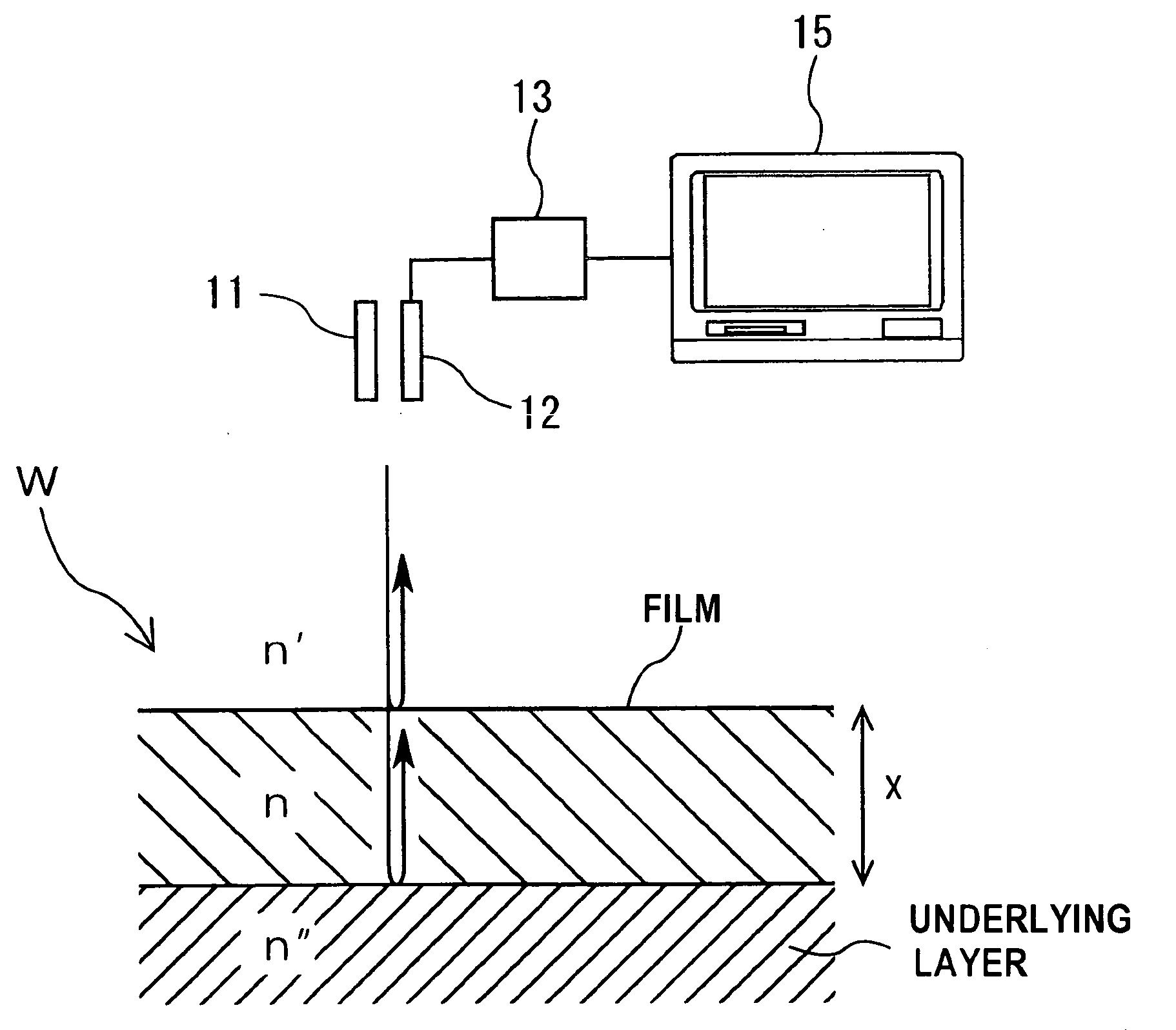
[0136]Embodiments of the present invention will be described below with reference to the drawings. FIG. 8 is a schematic view showing the principle of a polishing progress monitoring method according to an embodiment of the present invention. As shown in FIG. 8, a substrate W to be polished has a lower layer (e.g., a silicon layer) and a film (e.g., an insulating film, such as SiO2, having a light-transmittable characteristic) formed on the underlying lower layer. A light-applying unit 11 and a light-receiving unit 12 are arranged so as to face a surface of the substrate W. The light-applying unit 11 is configured to apply light in a direction substantially perpendicular to the surface of the substrate W, and the light-receiving unit 12 is configured to receive the reflected light from the substrate W. A spectroscope 13 is coupled to the light-receiving unit 12. This spectroscope 13 measures intensity of the reflected light, received by the light-receiving unit 12, at each wavelengt...


PUM

PropertyMeasurementUnit
wavelengthsaaaaaaaaaa
relative reflectancesaaaaaaaaaa
wavelengthaaaaaaaaaa

Abstract

A method of producing a diagram for use in selecting wavelengths of light in optical polishing end point detection is provided. The method includes polishing a surface of a substrate having a film by a polishing pad; applying light to the surface of the substrate and receiving reflected light from the substrate during the polishing of the substrate; calculating relative reflectances of the reflected light at respective wavelengths; determining wavelengths of the reflected light which indicate a local maximum point and a local minimum point of the relative reflectances which vary with a polishing time; identifying a point of time when the wavelengths, indicating the local maximum point and the local minimum point, are determined; and plotting coordinates, specified by the wavelengths and the point of time corresponding to the wavelengths, onto a coordinate system having coordinate axes indicating wavelength of the light and polishing time.

Description

BACKGROUND OF THE INVENTION[0001]1. Field of the Invention[0002]The present invention relates to a polishing progress motoring method and a polishing apparatus, and more particularly to a polishing progress motoring method and a polishing apparatus for monitoring a change in thickness of a transparent insulating film during polishing of the film.[0003]The present invention also relates to a method and an apparatus for selecting wavelengths of light for use in an optical polishing end point detection of a substrate having a transparent insulating film.[0004]The present invention also relates to a method and an apparatus for detecting a polishing end point of a substrate having an insulating film, and more particularly to a method and an apparatus for detecting a polishing end point based on reflected light from a substrate. The present invention also relates to a polishing method and a polishing apparatus for polishing a substrate while monitoring reflected light from the substrate.[...

Claims


Application Information

Patent Timeline
Patent Type & Authority Applications(United States)
IPC IPC(8): B24B49/12
CPCB24B49/12B24B37/013
Inventor KOBAYASHI, YOICHISHIMIZU, NOBURUOHTA, SHINROUKIMBA, TOSHIFUMIKINOSHITA, MASAKI
Owner EBARA CORP
Why Eureka
Try Eureka