Voltage control at windfarms

a windfarm and voltage control technology, applied in adaptive control, process and machine control, instruments, etc., can solve the problems of violation of voltage limits at other locations, plurality of individual local windfarm controllers cannot control at the point of common coupling, and windfarms are remote from existing transmission lines of grid

Active Publication Date: 2010-04-15
GENERAL ELECTRIC CO
View PDF5 Cites 91 Cited by
  • Summary
  • Abstract
  • Description
  • Claims
  • Application Information

AI Technical Summary

Benefits of technology

[0010]The present invention relates to a system and method for voltage control of a system of multiple windfarms including transmission lines.
[0011]Briefly in accordance with one aspect of the present invention a system of windfarms is provided, adapted for controlling voltage at a reference point on the system of windfarms including a transmission line providing a connection to a grid for one or more coupled local windfarms wherein voltage control at the reference point is subject to constraints on maintaining designated system parameters within specified tolerance. The embodiment of the system may include a plurality of local windfarms. Each of the local windfarms may include one or more individual wind turbine generators WTG with an individual output transformer. A collector system for each local windfarm including a collector transformer joined through a network of conductors with the individual WTGs and their individual output transformers may be provided. One or more collector systems may be joined through a network of conductors at a collector substation. The collector system transformer steps up voltage to a level for suitable for the transmission line. One or more substations may be connected to one or more transmission lines further connecting the collector systems to a grid. The system may further include a local windfarm controller for each local windfarm, adapted for controlling generation of reactive power for each individual generator of a local windfarm to operate within the voltage and thermal limits of the individual wind turbine generator. The system may further include a voltage reference point on the system for voltage control and at least one constraint point on the system in addition to the voltage reference point, wherein an operating parameter for the system of windfarms is constrained by the control system. A master controller for the windfarm system control system is provided. The master controller is adapted for generating real power and reactive power command for each local wind farm controller for controlling voltage at the voltage reference point to a designated value subject to at least one additional constraint on an operating parameter for the system of windfarms at the constraint point.

Problems solved by technology

Increasingly, as windfarms are being located in geographic areas with valuable wind characteristics, the windfarms are remote from existing transmission lines of a grid.
However, the plurality of individual local windfarm controllers cannot control at the point of common coupling because the power-related parameters at that point are a combination of the outputs from all of the individual windfarms.
However, voltage regulation at a single point associated with the output from the multiple windfarms may lead to violation of voltage limits at other locations on the transmission line or within individual windfarms. FIG. 1 illustrates a voltage profile at various points on a transmission line between a point of common coupling (POCC) with a windfarm and a point of interconnection (POI) with a grid.
Further, the windfarm control algorithm may be subject to various constraints, one of which may be a power factor of approximately 0.95 at the POCC.
Such methods, however, have not addressed loss optimization for multiple windfarms including a transmission line between the windfarms and a point of interconnection (POI) with a grid.

Method used


Image

  • Voltage control at windfarms
  • Voltage control at windfarms
  • Voltage control at windfarms

Examples


Embodiment Construction

[0029]The following embodiments of the present invention have many advantages, including

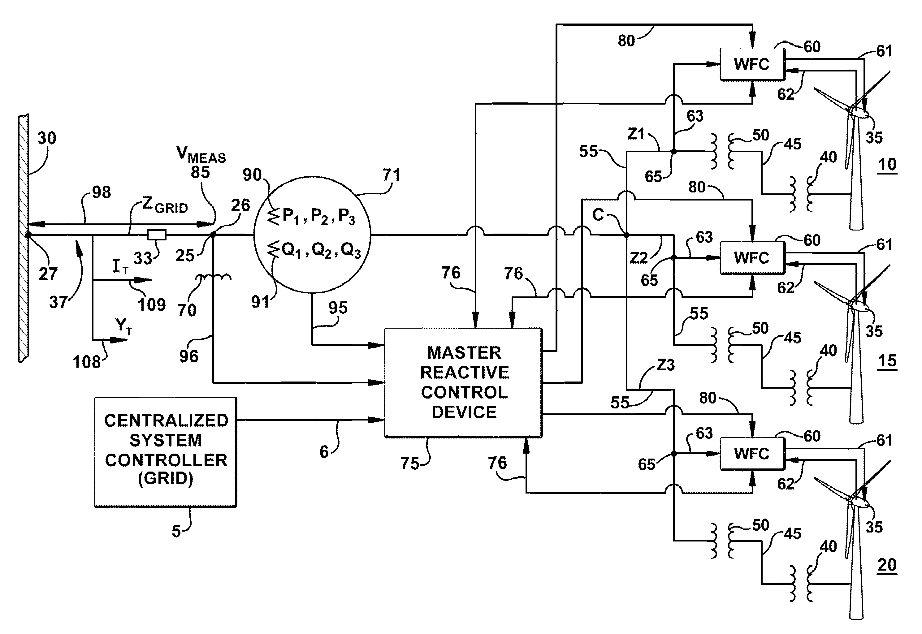
[0030]The present invention may regulate the output of a system of multiple coupled windfarms, connected to a grid of an electrical power system, so as to jointly regulate a single common point of electrical coupling through coordinated real power, reactive power and voltage response. A windfarm system control device may monitor a common measurement point for power-related parameters (such as currents, voltage, real power, reactive power and power factor) where the parameter value at the measurement point is an aggregate sum of the contributions for each local windfarm. Line drop compensation may be applied, if necessary, to compensate for real power losses, reactive power losses, and voltage drops that may be required if the measurement point is not at the point in the system at which the combined output of the windfarms is to be regulated. The windfarm system control device may incorporate a re...


PUM


Abstract

A voltage control arrangement for a system of multiple windfarms with transmission lines. Voltage is regulated at a point of regulation on the system, such as a high voltage substation or other system bus. Regulation is achieved at the point of regulation by sensing the voltage, comparing to a reference voltage, and adjusting the reactive power output of the wind turbines and other equipment in the system. The regulation point may be shifted to another point if needed to respect voltage limits at that points of the system after attempting to shift reactive load to restore voltage within limits at the other points in the system. The reference voltage may be adjusted to minimize losses for the system of multiple windfarms and transmission lines. A loss optimizing algorithm is applied to the combined multiple windfarm and transmission line to shift reactive load among local windfarms to minimize losses and to shift reactive load among individual wind turbines within an individual windfarm.

Description

BACKGROUND OF THE INVENTION[0001]The invention relates generally to operation of windfarms within an electric grid and more specifically to voltage control for a system of multiple windfarms.[0002]Typically, an electric power system includes a plurality of power generation assets, which are spread over a geographic area. The electric power system also includes systems that consume power (loads) that may also be spread over the geographic area. The electric power system also includes a grid, a network of electric power lines and associated equipment used to transmit and distribute electricity over a geographic area. The infrastructure of the grid, may include, but is not limited to devices for interconnection, control, maintenance, and improvement of the electric power system operation. Typically, the electric power system includes a centralized control system operatively connected to the power generation assets for controlling a power output of each of the power generation assets, f...

Claims


Application Information

Patent Timeline
Patent Type & Authority Applications(United States)
IPC IPC(8): G05B13/04G06F1/28
CPCF03D9/003H02J3/16Y02E40/34Y02E10/72Y02E10/763H02J3/386F03D9/255F03D9/257H02J2203/20H02J2300/28H02J3/381Y02E10/76Y02E40/30Y02E40/70Y02E60/00Y04S10/50Y04S40/20H02J3/50
Inventor LARSEN, EINAR V.WALLING, REIGH A.CLARK, KARA
Owner GENERAL ELECTRIC CO
Why Eureka
Try Eureka