
System for Reducing The Braking Distance of a Vehicle

a technology for reducing the braking distance and vehicles, applied in the field of vehicle brakes, can solve the problems of taking time and lengthening the stopping distance, affecting the safety of vehicles, and no precise data about the current position

Inactive Publication Date: 2010-04-15
CONTINENTAL TEVES AG & CO OHG
View PDF3 Cites 57 Cited by
  • Summary
  • Abstract
  • Description
  • Claims
  • Application Information

AI Technical Summary

Benefits of technology

[0012]The system according to aspects of the invention reduces the stopping distance of a vehicle by analysing data which are received via a vehicle-to-vehicle communication, and the surroundings 8 of the vehicle are analysed, and vehicle-specific data are transmitted and integrated into an existing safety concept with a dynamic surroundings model.
[0014]The expansion of the dynamic surroundings model, carried out by the system, by adding the objects which are located outside the sensing range of the radar sensors, lidar sensors and camera sensors, by means of the data which are received via a vehicle-to-vehicle communication, is particularly advantageous since this increases the “viewing range”.
[0018]In a further particularly preferred refinement, the acceleration information is analysed and evaluated in order to reduce the reaction time.
[0020]The present invention relates to the precondition that hazardous traffic situations, in particular mass pile-ups and accidents in oncoming traffic and intersecting traffic, can be effectively avoided only if as far as possible all of the vehicles which are located in a specific area of the surroundings are included in a safety concept and if the position of all the involved vehicles is made available as precisely as possible.

Problems solved by technology

This takes time and lengthens the stopping distance.
A disadvantage with these known systems is that vehicles which are located only in half of the area to the rear of a transmitting vehicle are provided with information and that no precise data are available about the current position of the vehicles in question.
The assessment of a risk of collision is therefore also subject to uncertainties.
Vehicles which are located in half of the area in front of the transmitting vehicle are not provided with any information even if they are approaching the location of the accident in the oncoming traffic and are confronted with an unexpected risk within a short time.
Despite the very good performance of the system, system-related problems arise here, such as the fact that stationary vehicles or objects are not detected by the beam sensors.
As a result it is only possible to make a classification with respect to the beam sensor properties of the object, and it is not possible to make one in terms of what the object actually is or whether it is at all an object on the road, next to it, below it or above it.
For this reason, owing to the high level of uncertainty it is not possible to initiate any strong autonomous braking processes.
Furthermore, carriageway markings are not used in order to ensure an improved situation analysis, and the range of the sensor is continuously limited by vehicles or objects in the surroundings.

Method used


Image

  • System for Reducing The Braking Distance of a Vehicle
  • System for Reducing The Braking Distance of a Vehicle

Examples


Embodiment Construction

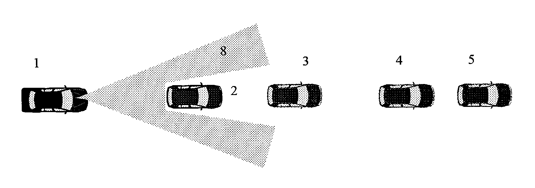
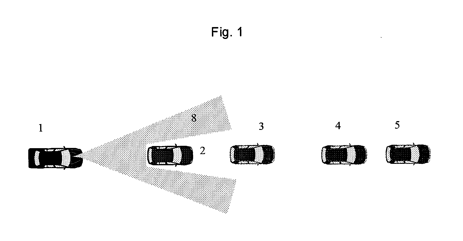
[0028]FIG. 1 represents a driving situation in front of a vehicle 1 in which the front vehicle area is monitored by the vehicle 1 by means of the sensors 8. If the vehicle-to-vehicle communication is made use of in addition to the radiation sensors 8, a highly expanded surroundings model which can be adapted dynamically is obtained.

[0029]There is no visibility restriction as a result of the vehicle-to-vehicle communication. Data can be exchanged between vehicles and other vehicles or an infrastructure around corners, for example can pass by intersections and other vehicles. A transmitting vehicle no longer has to be identified separately as a vehicle since the type of vehicle is also transmitted, and since stationary vehicles also transmit their position they are also detected.

[0030]If a vehicle 3, 4, 5 travelling in front brakes and the traction controller is deployed, the estimated coefficient of friction can also be transmitted and the intervention strategy and warning strategy c...


PUM


Abstract

Method for reducing the stopping distance of a vehicle, wherein data which are received via a vehicle-to-vehicle communication are analysed, and a surroundings analysis for the driver's own vehicle is carried out, and vehicle-specific data are transmitted and integrated into an existing safety concept.

Description

CROSS REFERENCE TO RELATED APPLICATIONS [0001]This application is the U.S. national phase application of PCT International Application No. PCT / EP2007 / 060914, filed Oct. 12, 2007, which claims priority to German Patent Application No. DE 102006049103.3, filed Oct. 13, 2006, the contents of such applications being incorporated by reference herein.BACKGROUND OF THE INVENTION [0002]1. Field of the Invention[0003]The invention relates to the field of vehicle brakes and relates, in particular, to a system for reducing the braking distance of a vehicle, in which braking is prepared and carried out when a predefined event occurs.[0004]2. Description of the Related Art[0005]EP 1081004 A2 discloses a sensing system of a vehicle which detects obstacles in the direction of travel or near to the direction of travel of the vehicle. Sensors which are mounted on the vehicle supply characteristic parameters for the state of the vehicle. Furthermore, sensors are assigned to the brake pedal and to the...

Claims


Application Information

Patent Timeline
Patent Type & Authority Applications(United States)
IPC IPC(8): B60W40/02G06F17/50G01S13/00
CPCB60W40/02
Inventor LUKE, STEFANPFEIFFER, JURGENSTRAUSS, MATTHIAS
Owner CONTINENTAL TEVES AG & CO OHG
Learn More