Paint roller with tubular frame

a tubular frame and paint roller technology, applied in the direction of liquid surface applicators, decorative arts, artistic surface treatment, etc., can solve the problems of increased material cost, inability to easily rotate about the axle, and still may be easily deformed, so as to save material cost and facilitate use. , the effect of durable us

Inactive Publication Date: 2010-04-22
HU REN MIN
View PDF3 Cites 3 Cited by
  • Summary
  • Abstract
  • Description
  • Claims
  • Application Information

AI Technical Summary

Benefits of technology

[0014]1. Selected portions of said tubular axle (1) are processed through reel stretching process by roll mill to lengthen, flatten, and bend said selected portions to form said bent portions (2), which are further processed through stamping process by stamping machine, cross sections of said bent portions is defined as a width larger than a height within a flattened configuration. Tubular axle (1) is therefore light weight and durable in use.
[0015]2. Tubular axle (1) carries a weight only ⅓ of a solid axle with a same diameter. Material cost can be saved.
[0016]3. To pull and stretch said tubular axle (1) through modes, or to weld said tubular axle (1) one by one, neither acid pickling nor phosphating treatment is required in manufacturing.
[0017]4. No other components need to be processed through any treatments to join together to the paint roller with tubular frame. Thereby, the tubular axle can be completely adapted to paint roller instead of old fashioned items.
[0018]5. Said tubular axle (1) is used instead of the solid axle

Problems solved by technology

1. Not to meet environmental protection and green product requirements: due to the solid axle (20) is substantially made from traditional iron wire that must be shaped-through acid pickling and straight line wire drawing processes. Mass of hydrochloric acid and calcium carbonate consumed impacts on the environment.
2. Solid axle (20) is used as a main body of the paint roller with tubular frame. Materials for m

Method used


Image

  • Paint roller with tubular frame
  • Paint roller with tubular frame
  • Paint roller with tubular frame

Examples


Embodiment Construction

[0025]The description is described according to the appended drawings hereinafter.

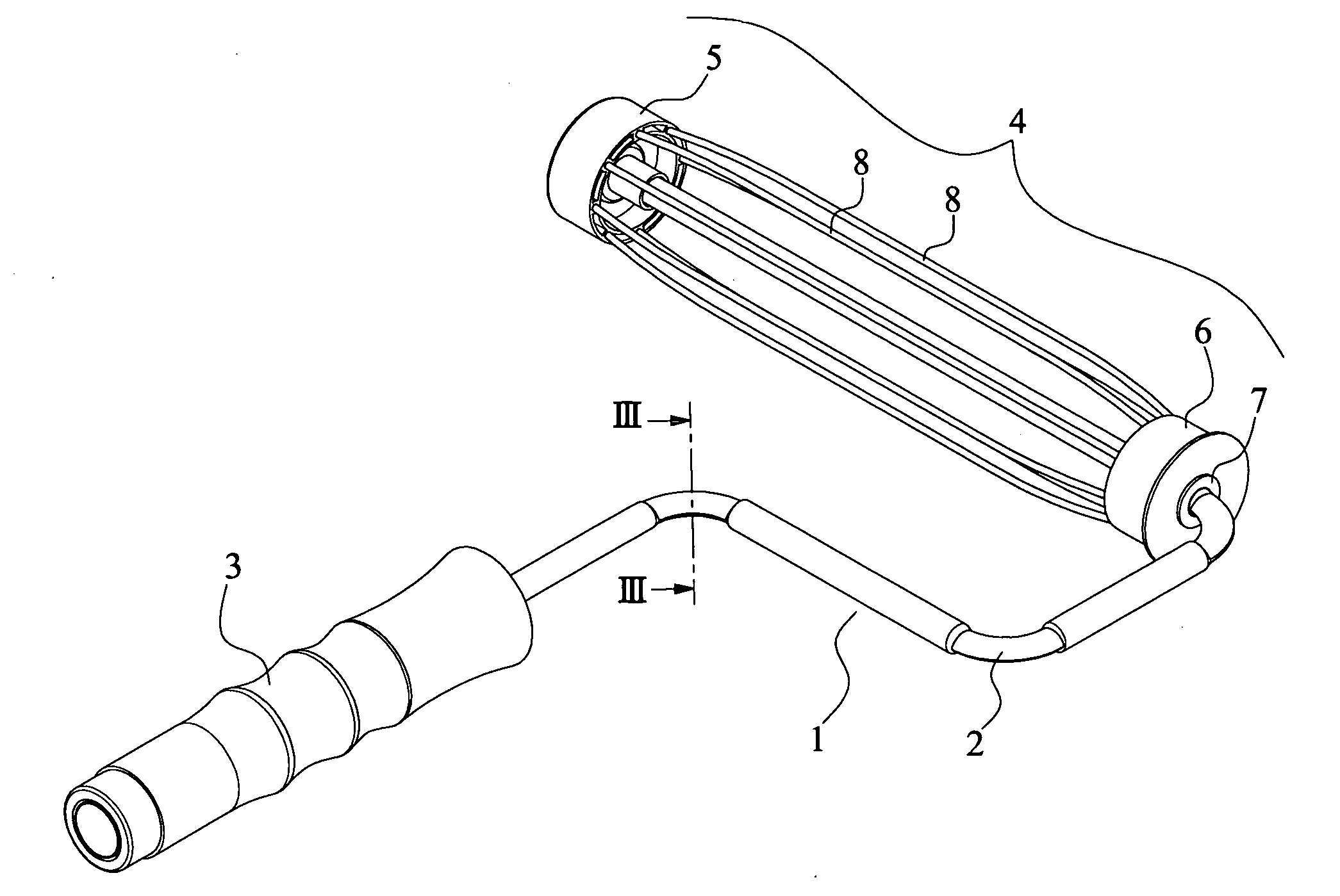
[0026]As shown in FIGS. 2-5, a frame includes, at least, a tubular axle (1); a cylinder (4) at a distal end of said axle (1); and

[0027]A handle (3) at a proximal end of said axle (1); characterized in that:

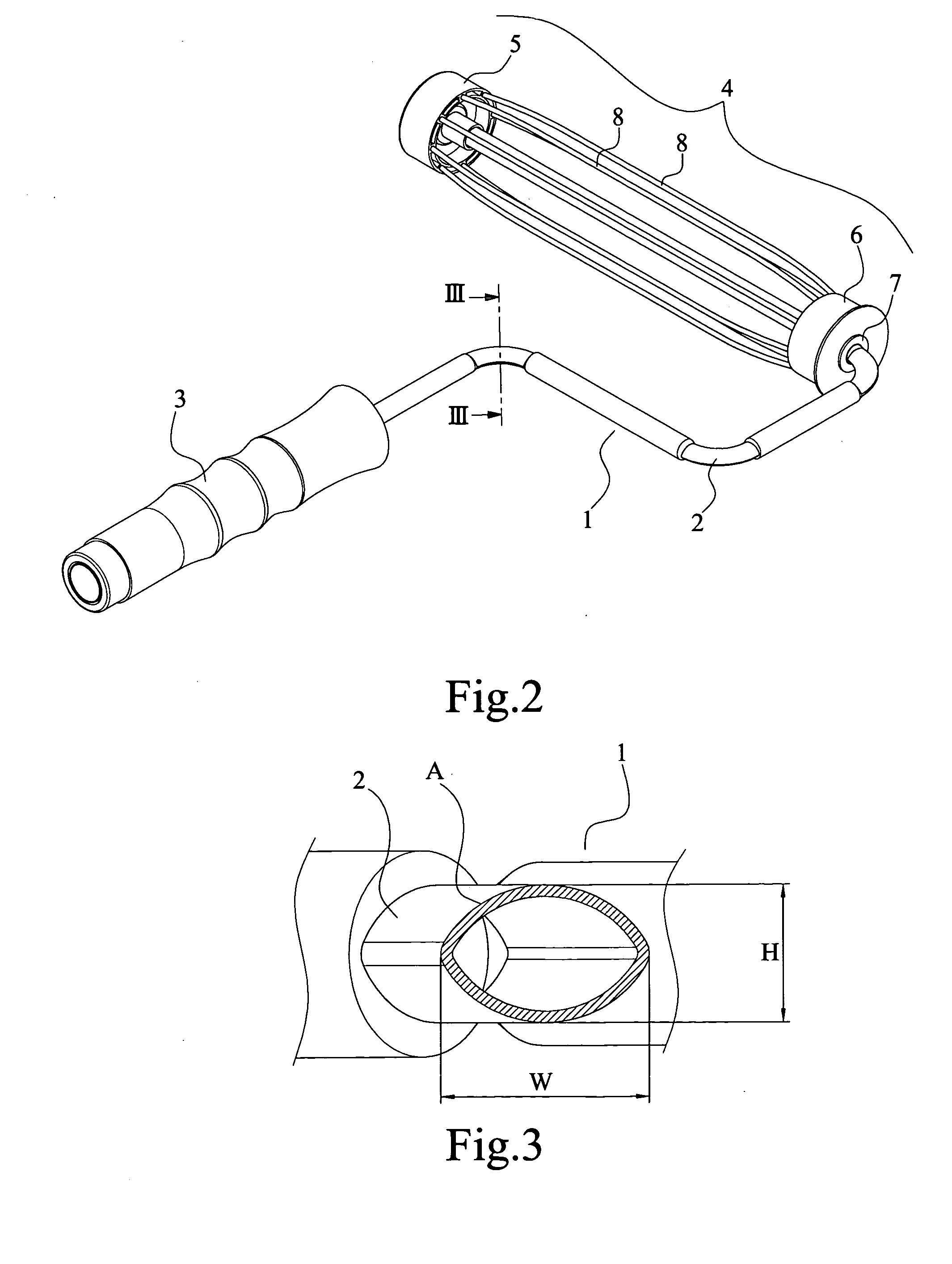
[0028]Being processed through roll mill to reel stretch said axle (1) to form bent portions (2), which further processed through stamping machine to lengthen, flatten and bend the bent portions (2), where a cross section of said bent portions (2) shown a width larger than a height shaped in an overall flattened configuration (A). (As shown in FIG. 3)

[0029]As above, selected portions of said tubular axle (1) are processed through reel stretching process by roll mill to lengthen, flatten, and bend said selected portions to form said bent portions (2), which are further processed through stamping process by stamping machine, cross sections of said bent portions is defined as a width larger than a height...


PUM


Abstract

The present invention is to provide a paint roller with tubular frame processed through less contamination process, lower material cost, light weight but durable in use. The present invention is to provide a paint roller with tubular frame includes, at least, a tubular axle (1); a cylinder (4) at a distal end of said axle (1); and a handle (3) at a proximal end of said axle (1); characterized in that: being processed through roll mill to reel stretch said axle (1) to form bent portions (2), which further processed through stamping machine to lengthen, flatten and bend the bent portions (2), where a cross section of said bent portions (2) shown a width larger than a height shaped in an overall flattened configuration (A).

Description

FIELD OF THE INVENTION[0001]The present invention is related to an improved structure about paint roller with tubular frame for painting.BACKGROUND OF THE INVENTION[0002]As shown in FIG. 1, a perspective view of an old fashioned paint roller with tubular frame is illustrated. Said paint roller (10) includes a solid axle (20); a cylinder (30) at a distal end of said axle (20); and a handle (40) at a proximal end of said axle (20). By means of said handy, old fashioned item, users can paint walls, floors, and other surfaces.[0003]But, users became aware that drawbacks of the old fashioned item appeared as follows:[0004]1. Not to meet environmental protection and green product requirements: due to the solid axle (20) is substantially made from traditional iron wire that must be shaped-through acid pickling and straight line wire drawing processes. Mass of hydrochloric acid and calcium carbonate consumed impacts on the environment.[0005]2. Solid axle (20) is used as a main body of the p...

Claims


Application Information

Patent Timeline
IPC IPC(8): B05C17/02
CPCB05C17/02
Inventor HU, REN-MIN
Owner HU REN MIN
Why Eureka
Try Eureka