
Apparatus and method for rotating a shaft

a technology of rotating shafts and rotating gears, which is applied in the direction of propellant elements, waterborne vessels, vessel construction, etc., can solve the problems of static shafts being susceptible to distortion, hot, damage to turning gears, etc., and achieve the effect of reducing the structural loading requirements of the apparatus and facilitating selective engagemen

Active Publication Date: 2010-04-22
GALLOWAY ERIC
View PDF13 Cites 30 Cited by
  • Summary
  • Abstract
  • Description
  • Claims
  • Application Information

AI Technical Summary

Benefits of technology

[0010]As the rotary drive arrangement is fixed, the apparatus is not required to move the mass of the rotary drive arrangement when engaging the transmission system with the shaft. Accordingly, reaction loads generated as a result of shock loading on the apparatus may be mitigated or substantially eliminated.
[0014]The transmission system may comprise a pivot arm or the like. The provision of a pivot arm facilitates selective engagement between the rotary drive arrangement and the shaft.
[0015]The transmission system may be substantially balanced about the drive shaft axis, this assisting in substantially reducing the structural loading requirements of the apparatus in the event of shock loading.
[0020]Furthermore, the second driven member may be adapted to engage a further driven member on the shaft to be rotated. For example, the further driven member may comprise a shaft gear fixed to the shaft, the shaft gear adapted to facilitate rotation of the shaft by the second driven member. Where, for example, the second driven member and further driven member comprise gears, the gear profiles may be configured to facilitate meshing of the second driven member and shaft gear. In particular, the gear profiles may advantageously be formed to reduce or overcome tip interference.
[0022]The actuator may be of any appropriate form. For example, the actuator may comprise a screw jack. Alternatively, or in addition, the actuator may comprise a hydraulic ram, pneumatic actuator or other suitable actuator. Advantageously, location of the rotary drive arrangement off the transmission system reduces the load requirement of the actuator and facilitates the use of a smaller, more compact actuator. Furthermore, shock loading transmitted to the actuator may be reduced.

Problems solved by technology

During operation, the shaft can often become hot and may be subject to a degree of expansion and it has been found that, when rotation of the shaft is stopped, the static shaft may be susceptible to distortion in the form of sagging, bowing or other damaging temperature effects.
It will be recognized that significant loads may be transmitted through the turning gear and the shaft and, for example, with regard to larger vessels, it has been found that reaction loads generated in the turning gear mechanism due to shock loading can result in damage to the turning gear.

Method used


Image

  • Apparatus and method for rotating a shaft
  • Apparatus and method for rotating a shaft
  • Apparatus and method for rotating a shaft

Examples


Embodiment Construction

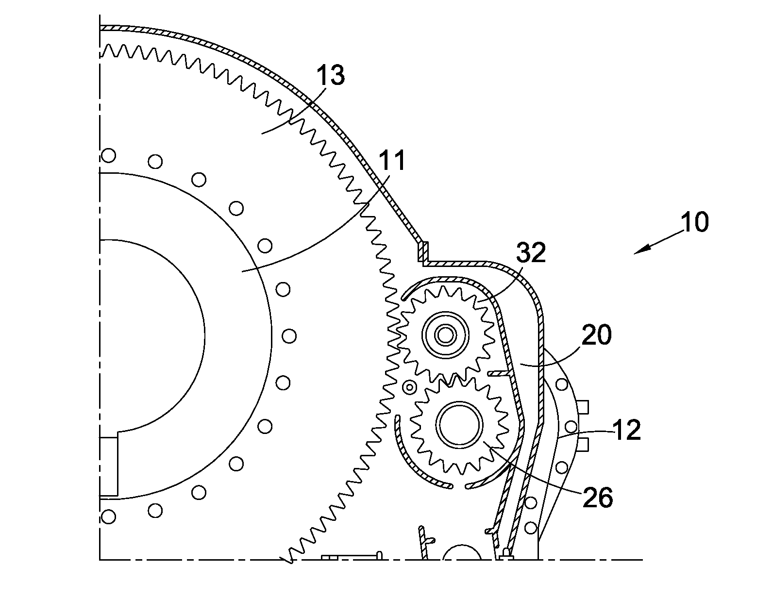
[0034]The Figures show turning gear apparatus 10 in accordance with an embodiment of the present invention. The apparatus 10 is adapted to engage and rotate a shaft, such as a propeller shaft 11 (FIGS. 4 and 5) of a sea-going vessel.

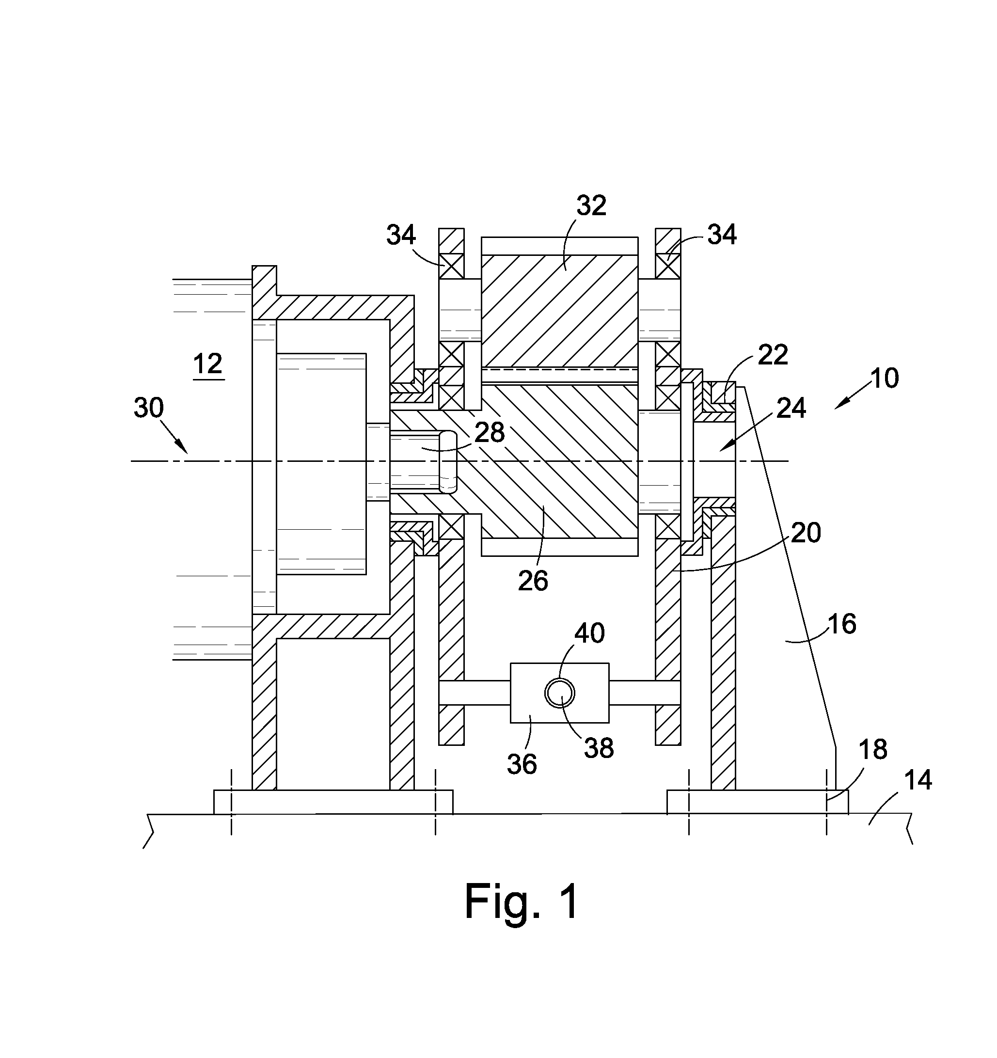
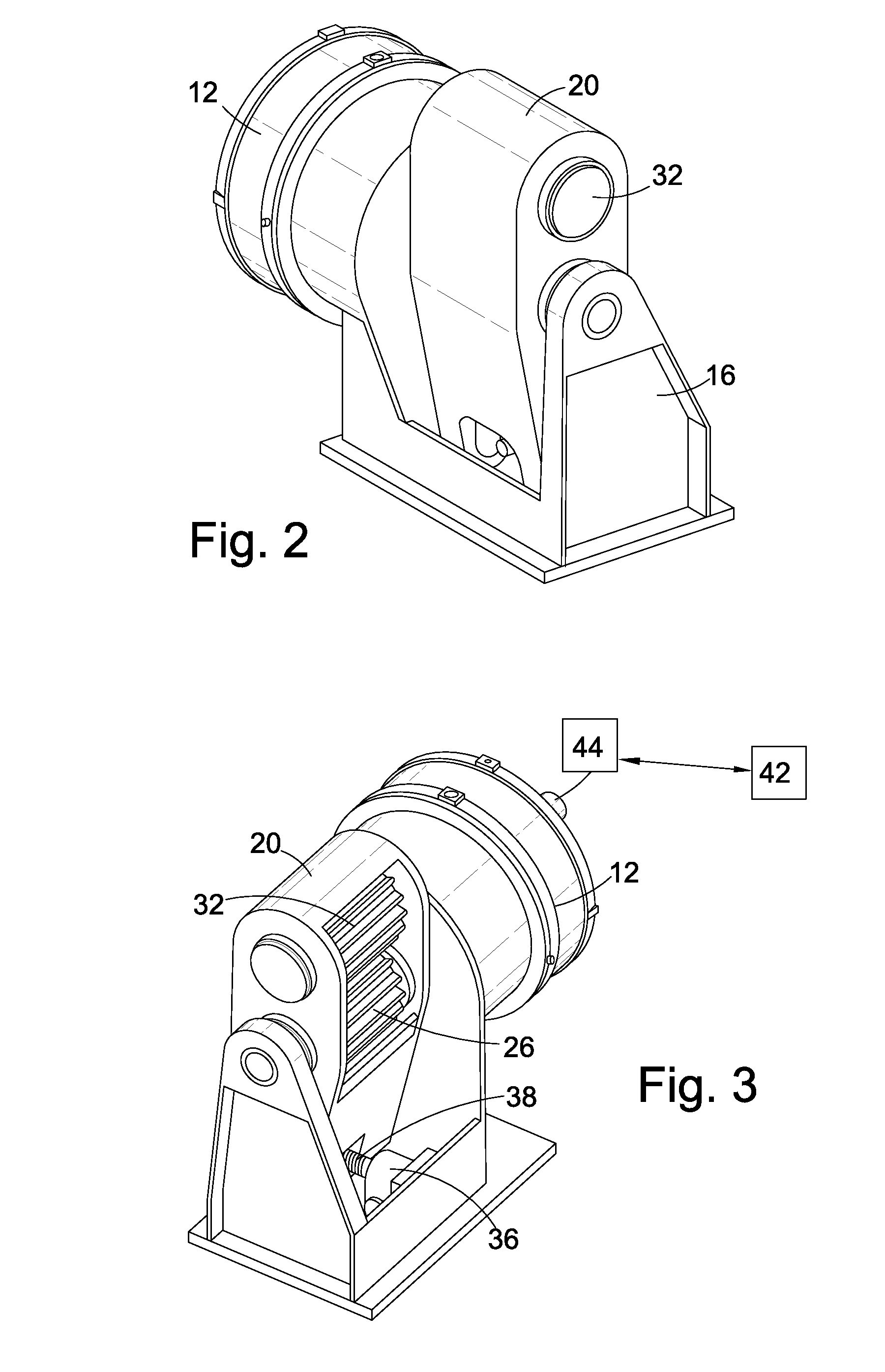
[0035]With reference to FIGS. 1 to 3, the apparatus 10 comprises a rotary drive arrangement in the form of a hydraulic motor 12 which is fixed to a vessel hull 14 via a base bracket 16. The bracket 16 is secured to the hull 14 by a bolted connection 18, though any suitable arrangement for securing the bracket 16 may be used.

[0036]The apparatus 10 further comprises a transmission system which includes a pivot arm 20 coupled to the bracket 16 by a bearing 22. The bearing 22 comprises a radial bearing, though any suitable bearing member may be employed and the pivot arm 20 is thus adapted for rotational movement about a pivot axis 24.

[0037]The apparatus 10 further comprises a first driven member in form of a pinion gear 26 mounted on a drive shaft 28 of the...


PUM


Abstract

Turning gear apparatus for rotating a shaft comprises a rotary drive arrangement and a transmission system including a pivot arm. The rotary drive arrangement is fixed, for example to a vessel hull, and the pivot arm is pivotable between a first, shaft-disengaged, position and a second, shaft-engaged position where the rotary drive arrangement is operably coupled to the shaft, thereby permitting control over rotation of the shaft by the rotary drive arrangement.

Description

PRIORITY / CROSS-REFERENCE TO RELATED APPLICATIONS[0001]This application claims the priority date of the provisional application entitled APPARATUS AND METHOD FOR ROTATING A SHAFT filed by Eric Galloway on Oct. 20, 2008 with application Ser. No. 61 / 106,173, the disclosure of which is incorporated by reference.FIELD OF THE INVENTION[0002]The invention generally relates to an apparatus and method for rotating a shaft and, in particular, but not exclusively, to turning gear for use in a sea-going vessel.BACKGROUND OF THE INVENTION[0003]A number of systems have been developed to drive rotation of the propeller shaft or shafts of a sea-going vessel. For example, a steam turbine, gas turbine, combustion engine, electric motor or the like may be used to drive rotation of the shaft, either directly or via a reduction gearing arrangement.[0004]During operation, the shaft can often become hot and may be subject to a degree of expansion and it has been found that, when rotation of the shaft is s...

Claims


Application Information

Patent Timeline
Patent Type & Authority Applications(United States)
IPC IPC(8): F16H35/18F01D25/34
CPCB63H23/06B63H23/10Y10T74/19502B63H23/32B63H2023/348B63H23/30
Inventor GALLOWAY, ERIC
Owner GALLOWAY ERIC
Learn More