
Light-emitting diode lighting device

a technology of light-emitting diodes and lighting devices, which is applied in the direction of electric variable regulation, process and machine control, instruments, etc., can solve the problems of difficult to provide the desired temperature characteristic for the first switching element, and achieve the effect of reducing the capacitance of the smoothing capacitor, increasing the number of ripples contained in the rectified voltage, and circuit efficiency

Inactive Publication Date: 2010-04-22
TOSHIBA LIGHTING & TECH CORP +1
View PDF4 Cites 5 Cited by
  • Summary
  • Abstract
  • Description
  • Claims
  • Application Information

AI Technical Summary

Benefits of technology

The present invention provides a LED lighting device that includes a direct-current power supply, a step-down chopper, a self-excited drive signal generation circuit, and a turn-off circuit. The step-down chopper includes an input terminal connected to the direct-current power supply, an output terminal connected to the load, a first circuit including an impedance means and a first inductor connected in series, and a second circuit including a second inductor and a diode connected in series. The self-excited drive signal generation circuit includes a second inductor magnetically coupled with the first inductor of the step-down chopper and applies the voltage induced in the second inductor as a drive signal to keep the switching element on. The turn-off circuit includes a comparison means and a switch element that detects the voltage of the impedance means and turns off the switching element when the detected voltage exceeds a reference value. The LED lighting device has a satisfactory temperature characteristic and a small amount of variation in output current.

Problems solved by technology

Moreover, since the temperature characteristic of the first switching element is determined by the temperature characteristic of the transistor, it is disadvantageously difficult to provide a desired temperature characteristic for the first switching element.

Method used


Image

  • Light-emitting diode lighting device
  • Light-emitting diode lighting device
  • Light-emitting diode lighting device

Examples


Embodiment Construction

[0048]Embodiments of the present invention will be described below with reference to the accompanying drawings.

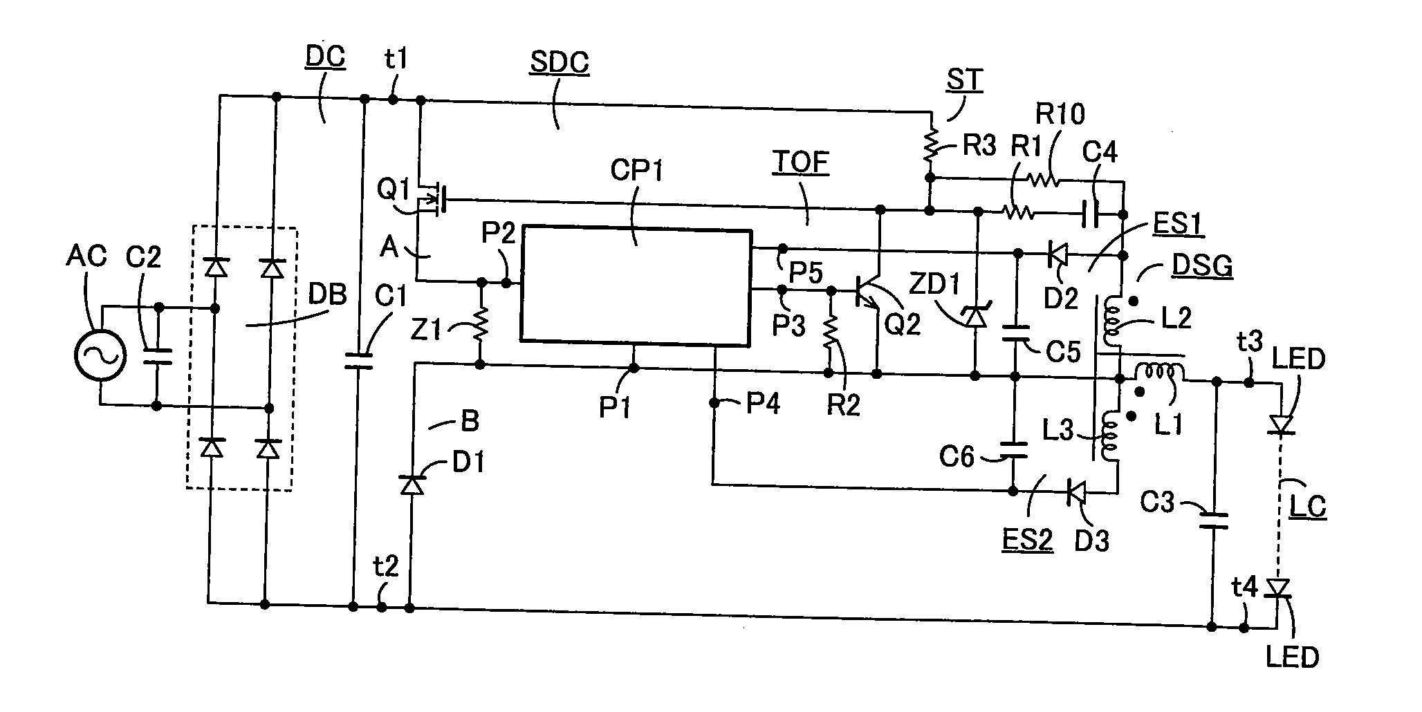
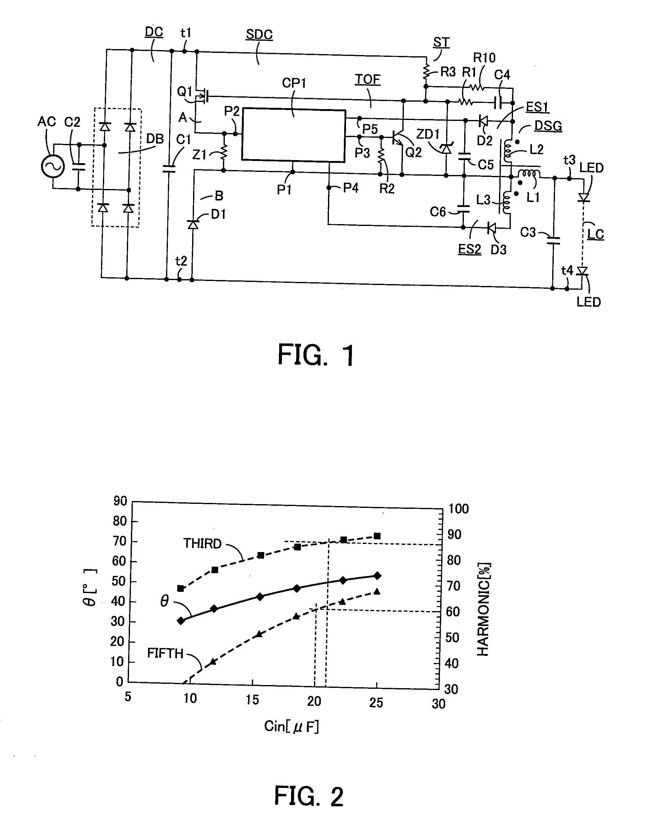
[0049]FIG. 1 is a circuit diagram showing an embodiment for embodying an LED lighting device according to the present invention.

[0050]The LED lighting device includes a direct-current power supply DC, a step-down chopper SDC, light-emitting diode LEDs, a self-excited drive signal generation circuit DSG and a turn-off circuit TOF. The self-excited drive signal generation circuit DSG and the turn-off circuit TOF constitute a self-excited drive circuit. In addition to these components, a start-up circuit ST is provided.

[0051]The direct-current power supply DC is provided with: a full-wave rectification circuit DB whose input terminals are connected to an alternating-current power supply AC such as a commercial alternating-current power supply having, for example, a rated voltage of 100V; and a smoothing capacitor C1. The smoothing capacitor C1 is connected to the output termin...


PUM


Abstract

There is provided an LED lighting device having a satisfactory temperature characteristic and a small amount of variation in output current. The step-down chopper is provided with a first circuit including the switching element, the impedance means and a first inductor connected in series and a second circuit including the first inductor and a diode connected in series. A self-excited drive signal generation circuit is provided with a second inductor magnetically coupled with the first inductor and applies a voltage induced in the second inductor to the switching element to keep the switching element on. A turn-off circuit outputs an output voltage when the voltage of the impedance means detected by a comparator exceeds the reference value, and the output voltage allows a switching element to turn on to short-circuit the output terminals of the self-excited drive signal generation circuit, resulting in that the switching element is turned off.

Description

INCORPORATION BY REFERENCE[0001]The present invention claims priority under 35 U.S.C. §119 to Japanese Patent Application Nos. 2008-269113, 2008-333679 and 2009-062254 filed on Oct. 17, 2008, Dec. 26, 2008 and Mar. 16, 2009, respectively. The contents of these applications are incorporated herein by reference in their entirety.FIELD OF THE INVENTION[0002]The present invention relates to a light-emitting diode lighting device provided with a step-down chopper.BACKGROUND OF THE INVENTION[0003]LED (light-emitting diode) lighting devices provided with a step-down chopper are known, one of which is disclosed in, for example, patent document (Japanese Patent Publication No. 4123886). In this type of LED lighting device, a resistor element having a low resistance is connected between a FET serving as a first switching element and a first inductor, and this resistor element is connected between the base and the emitter of a bipolar transistor serving as a second switching element. The colle...

Claims


Application Information

Patent Timeline
Patent Type & Authority Applications(United States)
IPC IPC(8): H05B41/36H05B44/00
CPCH05B33/089H05B33/0887H05B45/50H05B45/59
Inventor KAMATA, MASAHIKOOSAKI, HAJIMEOTAKE, HIROKAZUHAKUTA, SHINYAHIRAMATSU, TAKUROHIRAOKA, TOSHIYUKIIWAI, NAOKO
Owner TOSHIBA LIGHTING & TECH CORP
Learn More