
Battery state monitoring circuit and battery device

Active Publication Date: 2010-04-22
ABLIC INC
View PDF3 Cites 37 Cited by
  • Summary
  • Abstract
  • Description
  • Claims
  • Application Information

AI Technical Summary

Benefits of technology

[0011]A battery state monitoring circuit and a battery device according to the present invention have been devised in order to solve the above-mentioned problem. In the battery device that uses the cascade-connected battery state monitoring circuits, it is possible to securely inhibit charge even at a voltage lower than a minimum circuit operating voltage.
[0013]Therefore, at a power supply voltage lower than a voltage with which the circuit is not allowed to operate, it becomes possible to securely turn off a charge control transistor, to thereby inhibit charge.
[0014]According to the battery device including the battery state monitoring circuits of the present invention, in the battery device that uses the cascade-connected battery state monitoring circuits, there is an effect that charge is securely inhibited even at the power supply voltage lower than the minimum circuit operating voltage.

Problems solved by technology

The secondary battery has a risk of electrolyte leakage as a result of battery expansion after the battery has been charged excessively (overcharged).
Besides, characteristics of the battery itself deteriorate after the battery has been discharged excessively (overdischarged).
In particular, the lithium ion secondary battery is vulnerable to the overcharge and the overdischarge, and hence the protection circuit absolutely needs to be used for the lithium ion secondary battery.
Therefore, there arises a problem that, when a voltage of the secondary battery becomes lower than a minimum operating voltage of the logic circuits, voltages of the output terminals cannot be secured, which makes impossible to inhibit charge.

Method used


Image

  • Battery state monitoring circuit and battery device
  • Battery state monitoring circuit and battery device
  • Battery state monitoring circuit and battery device

Examples


Embodiment Construction

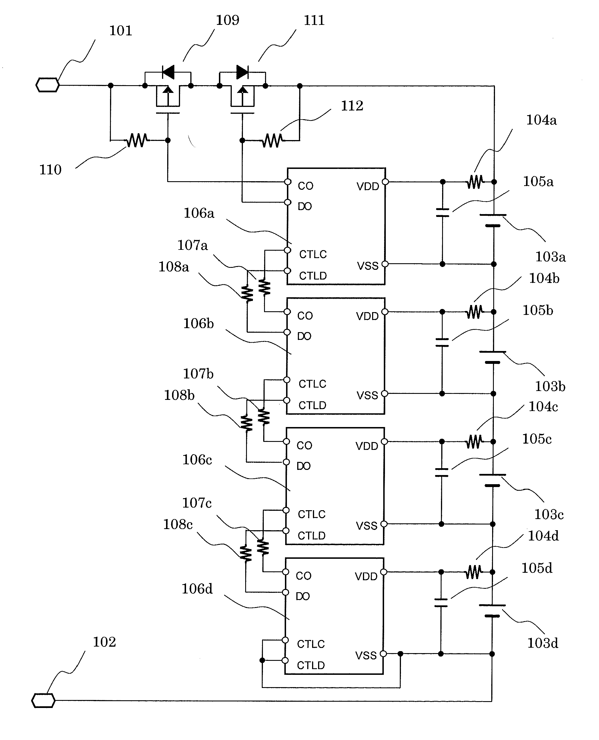
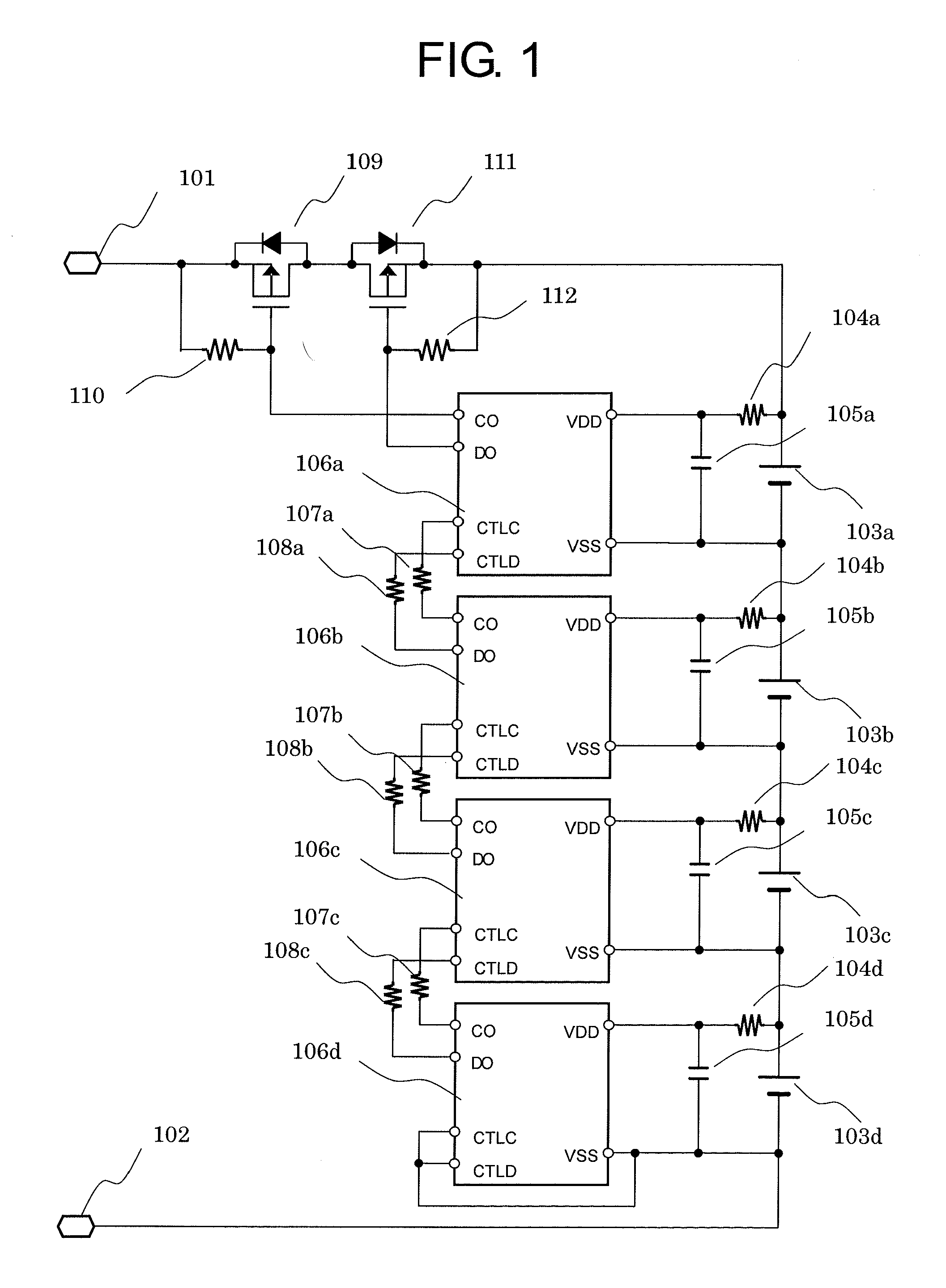
[0021]FIG. 1 illustrates a circuit diagram of a battery device according to the present invention. The battery device of FIG. 1 includes a plurality of cascade-connected battery state monitoring circuits. For the sake of simple description, FIG. 1 illustrates the battery device including four battery state monitoring circuits that are connected in series. Note that also in a case of a battery device including five or more battery state monitoring circuits that are connected in series, the same circuit configuration is made in which the corresponding number of battery state monitoring circuits are cascade-connected.

[0022]The battery device of FIG. 1 includes four batteries 103a to 103d that are connected in series, four battery state monitoring circuits 106a to 106d that are individually provided in correspondence with the batteries 103a to 103d, resistors for communication terminal connection 107a to 107c and 108a to 108c, a first transistor (charging P-channel transistor) 109, a se...


PUM


Abstract

Provided is a battery state monitoring circuit including a control circuit that applies, to a gate of a signal output transistor provided at a terminal for transmitting an overcharge detection signal, a potential at which the signal output transistor is turned off at a voltage lower than a minimum circuit operating voltage. Accordingly, in a battery device that uses the cascade-connected battery state monitoring circuits, charge is inhibited securely even at a power supply voltage lower than the minimum circuit operating voltage.

Description

RELATED APPLICATIONS[0001]This application claims priority under 35 U.S.C. §119 to Japanese Patent Application Nos. JP2008-270967 filed on Oct. 21, 2008 and JP2009-206359 filed on Sep. 7, 2009, the entire contents of which are hereby incorporated by reference.BACKGROUND OF THE INVENTION[0002]1. Field of the Invention[0003]The present invention relates to a battery state monitoring circuit that detects a voltage and an abnormality of a secondary battery including a nickel hydrogen battery and a lithium ion battery, and more particularly, to a battery state monitoring circuit capable of controlling charge and discharge to and from a battery pack containing a plurality of the secondary batteries that are connected in series.[0004]2. Description of the Related Art[0005]Nowadays, a secondary battery is used as power supply to a portable electronic device including a mobile phone, a notebook computer, and a portable game device. A lithium ion secondary battery is the mainstream of the sec...

Claims


Application Information

Patent Timeline
IPC IPC(8): H02J7/00G01R31/36H02J7/02
CPCH02J2007/0037H02J7/0026H02J7/00302H02J7/0014Y02E60/10H02J7/0048H02J7/00306H02J7/00032G01R31/3835H01M10/482
Inventor TANGE, YOSHIHISA
Owner ABLIC INC
Learn More