Light source device, and two-dimensional image display device

a two-dimensional image and display device technology, applied in the field of light source devices and can solve the problems of undesirable scale increase of conventional two-dimensional image display devices, and achieve the effects of reducing the number of gratings to be multiplexed on the diffraction part, low cost, and low cos

Active Publication Date: 2010-04-22
PANASONIC CORP
View PDF8 Cites 82 Cited by
  • Summary
  • Abstract
  • Description
  • Claims
  • Application Information

AI Technical Summary

Benefits of technology

[0044]According to the present invention, a light source device having plural coherent light sources is provided with a diffraction part that diffracts the respective lights emitted from the coherent light sources so that the lights propagate in the same optical path. Therefore, an optical system for multiplexing the respective lights emitted from the plural coherent light sources into coaxial beams can be downsized, thereby providing an ultracompact light source device.
[0045]Further, according to the light source device of the present invention, the light emitted from at least one coherent light source among the plural coherent light sources passes through the diffraction part without being diffracted by the diffraction part. Therefore, the number of gratings to be multiplexed on the diffraction part can be reduced, whereby the light source device can be constituted at low cost.
[0046]Further, according to the light source device of the present invention, the diffraction part is constituted by first and second diffraction gratings, and the second diffraction grating diffracts the lights from the plural coherent light sources so that these lights irradiate the same region of the first diffraction element, while the first diffraction grating diffracts the respective lights that pass through the second diffraction element so that these lights become coaxial beams. Therefore, it is possible to provide a compact light source device which can easily multiplex the lights from the plural light sources to be coaxial beams.
[0047]Further, according to the light source device of the present invention, the plural coherent light sources are disposed on the same submount. Therefore, heat radiation of the plural light sources can be carried out by heat radiation of the single submount, thereby facilitating heat radiation of the light source device.
[0048]Further, according to the light source device of the present invention, the diffraction part is regionally divided, and the divided regions of the diffraction part are respectively provided with plural gratings as well as functions of concave lenses. Therefore, the intensity distributions of the lights emitted from the diffraction part can be made uniform as well as the lights emitted from the plural coherent light sources can be easily converted into coaxial beams to be multiplexed. Further, the diffraction part having the light integrator that makes the intensity distributions of the lights emitted from the diffraction part uniform is more compact and can be fabricated using cheaper materials as compared with the conventional lens array, whereby the light source device can be realized at lower cost.
[0049]Further, according to the two-dimensional image display device of the present invention, the light source device is miniaturized using the diffraction element, whereby the two-dimensional image display device can be miniaturized.

Problems solved by technology

Consequently, the conventional two-dimensional image display device is undesirably increased in scale.

Method used


Image

  • Light source device, and two-dimensional image display device
  • Light source device, and two-dimensional image display device
  • Light source device, and two-dimensional image display device

Examples


embodiment 1

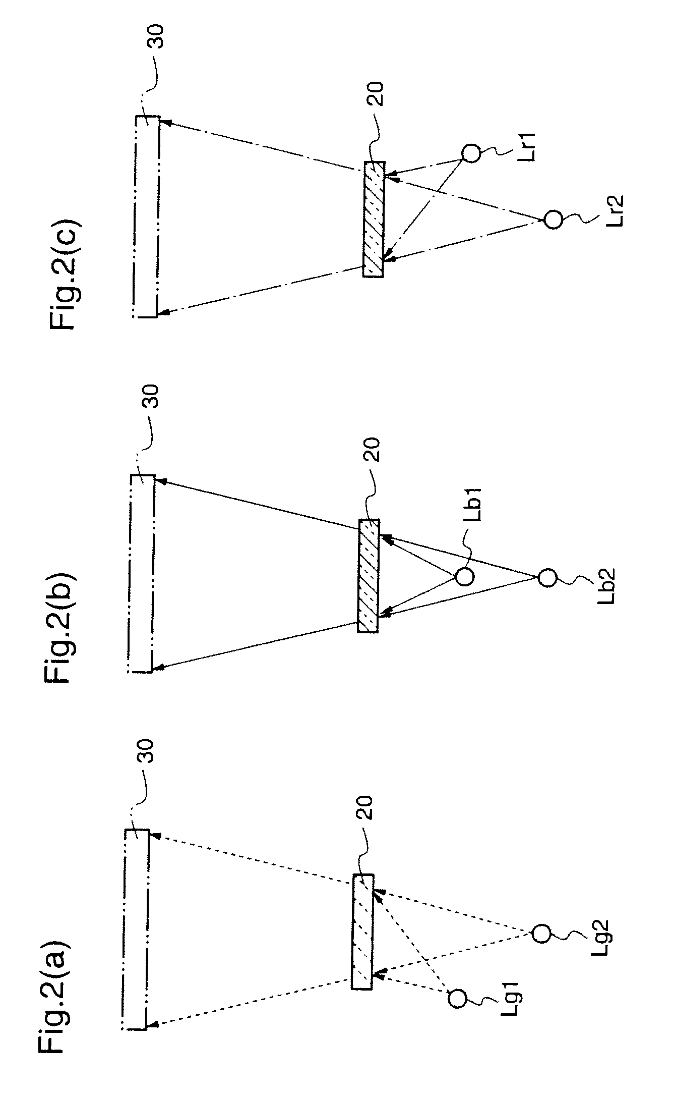
[0095]In this first embodiment, a description will be given of a light source device in which a single diffraction element diffracts light beams emitted from three coherent light sources that emit red, blue, and green lights so that these lights become coaxial beams, thereby to multiplex the respective lights. In the following description, “coaxial beams” means lights that propagate in the same optical path, and “light axis” means a center axis of a light propagation path.

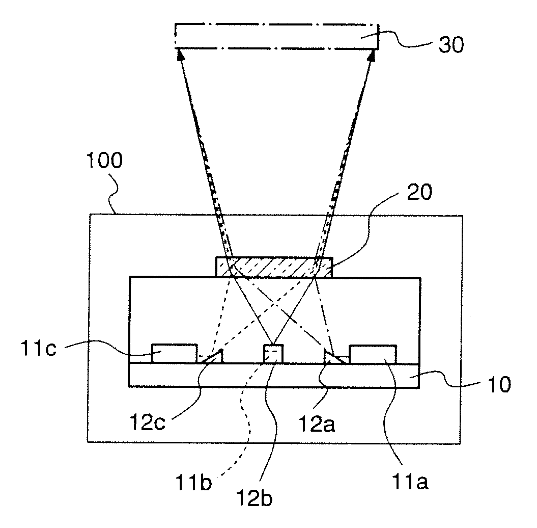
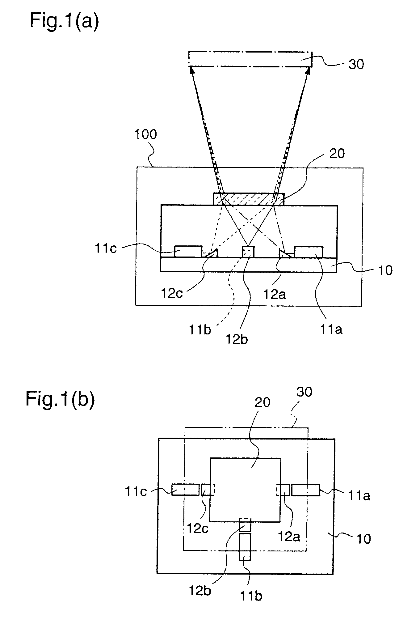
[0096]FIG. 1 is a diagram illustrating the construction of the light source device according to the first embodiment, wherein FIG. 1(a) is a side view and FIG. 1(b) is a plan view.

[0097]In FIG. 1, reference numeral 100 denotes a light source device according to the first embodiment, and the light source device 100 is used as a light source for a two-dimensional image display device. The light source device 100 includes coherent light sources, i.e., three semiconductor lasers 11a˜11c emitting red light, blue light, ...

embodiment 2

[0119]While in the first embodiment the diffraction part comprises a single diffraction element, in this second embodiment the diffraction part comprises two diffraction elements.

[0120]Initially, the construction of a light source device according to the second embodiment will be described. FIG. 5 is a diagram illustrating the construction of the light source device according to the second embodiment, wherein FIG. 5(a) is a side view and FIG. 5(b) is a plan view.

[0121]In FIG. 5, reference numeral 200 denotes a light source device according to the second embodiment. The light source device 200 is provided with a submount 10 such as a silicon substrate; three semiconductor laser light sources 21a˜21c which are disposed on the submount 10, and emit red light, blue light, and green light, respectively (hereinafter simply referred to as “laser light sources”); and a diffraction part 220 which is disposed above the submount 10 and diffracts the respective lights emitted from the three las...

embodiment 3

[0150]A light source device according to the third embodiment is constructed such that the diffraction part of the light source device according to the first embodiment has a function of a light integrator for making the light intensity distributions of the lights emitted from the respective laser light sources uniform.

[0151]FIG. 8 is a diagram illustrating the construction of the light source device according to the third embodiment, wherein FIG. 8(a) is a side view and FIG. 8(b) is a plan view.

[0152]With reference to FIG. 8, reference numeral 300 denotes a light source device according to the third embodiment. The light source device 300 includes laser light sources 11a, 11b, and 11c of red light, blue light, and green light, respectively, prisms 12a, 12b, and 12c for reflecting lights emitted from the red and green laser light sources 11a and 11c, a submount 10 for supporting these laser light sources and prisms, and a diffraction part 320 through which the lights emitted from th...


PUM


Abstract

There is provided a light source device which can miniaturize a two-dimensional image display device as small as possible. The light source device is provided with three coherent light sources (11a), (11b), and (11c) corresponding to red, blue, and green; prisms (12a) and (12c) for reflecting lights emitted from the coherent light sources (11a) and (11c); and a diffraction part (20) comprising a single volume hologram on which plural gratings are multiply-formed, which gratings diffract the light emitted from the coherent light source (11b), and the lights that are emitted from the coherent light sources (11a) and (11c) and reflected by the prisms (12a) and (12b) so that these lights propagate in the same optical path.

Description

TECHNICAL FIELD[0001]The present invention relates to a light source device and a two-dimensional image display device and, more particularly, to a light source device that realizes miniaturization of a two-dimensional image display device, and a compact two-dimensional image display device using the light source device.BACKGROUND ART[0002]In recent years, a two-dimensional image display device (laser display device) capable of representing bright colors has attracted attention. This device adopts three coherent light sources of red, green, and blue (e.g., laser light sources), and has a construction as shown in FIG. 13.[0003]In FIG. 13, reference numeral 600 denotes a two-dimensional image display device using conventional laser light sources. The two-dimensional image display device 600 comprises red, green, and blue laser light sources 601a, 601b, and 601c, beam expanders 602a, 602b, and 602c, light integrators 603a, 603b, and 603c, mirrors 604a and 604c, diffusion plates 606a, 6...

Claims


Application Information

Patent Timeline
Patent Type & Authority Applications(United States)
IPC IPC(8): G02B27/44G02B5/32G03B21/00G03B21/14H04N9/31
CPCG02B27/1053G02B27/1073G02B27/1093H04N9/315G03B21/14H04N9/3114H04N9/3129G02B27/149G03B21/208G03B33/12G03B21/00H04N5/74
Inventor KASAZUMI, KEN'ICHIMIZUUCHI, KIMINORIMORIKAWA, AKIHIROYAMAMOTO, KAZUHISA
Owner PANASONIC CORP
Why Eureka
Try Eureka