Unlock instant, AI-driven research and patent intelligence for your innovation.

Confocal microscope

a microscope and confocal technology, applied in the field ofconfocal microscopes, can solve the problems of more measurement time and time-consuming measurement, and achieve the effect of substantially reducing measurement tim

Inactive Publication Date: 2010-04-22
NIDEC TOSOK CORP
View PDF1 Cites 15 Cited by
  • Summary
  • Abstract
  • Description
  • Claims
  • Application Information

AI Technical Summary

Benefits of technology

[0018]Therefore, the measurement time can be substantially reduced, compared with the conventional case where, while the relative distance between the object to be measured and the objective lens is displaced in the Z direction, the amount of received light at each Z position should be stored and compared.

Problems solved by technology

In this way, it is necessary to obtain data while displacing the relative distance between the sample and the objective lens in the Z axis direction, so that there is a disadvantage that the measurement is time consuming.
In this case, the number of times of obtaining data is increased, so that there is a disadvantage that more measurement time is required.

Method used


Image

  • Confocal microscope
  • Confocal microscope
  • Confocal microscope

Examples


Embodiment Construction

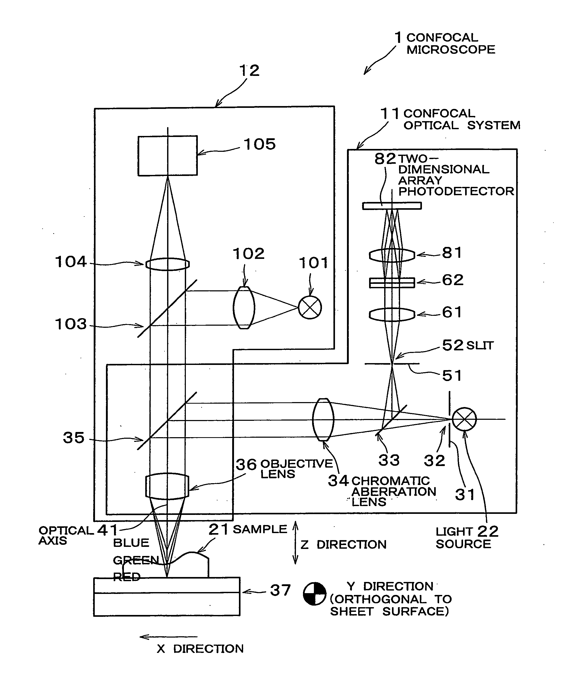
[0022]One embodiment of the present invention will be described below with reference to the drawings. FIG. 1 is a view showing a confocal microscope 1 according to this embodiment, and the confocal microscope 1 is an apparatus that measures the minute height and surface roughness of an object to be measured.

[0023]This confocal microscope 1 comprises a confocal optical system 11 and an observation optical system 12.

[0024]First, the confocal optical system 11 will be described.

[0025]This confocal optical system 11 is intended for obtaining the information of the height of the surface of a sample 21, as an object to be measured, in real time, and a light source 22 comprises a white light source, for example, a halogen lamp or a xenon lamp.

[0026]Light from this light source 22 is passed through the slit 32 of a slit plate 31, thus, linear bright lines are extracted. White light emitted from these linear bright lines is passed through a chromatic aberration lens 34 via a first half mirro...


PUM


Abstract

A confocal microscope that can reduce the measurement time is provided. Linear bright lines are extracted from the light of a light source. White light emitted from the linear bright lines is chromatically dispersed into continuous wavelength components by a chromatic aberration lens, which then irradiate a sample on a stage via an objective lens. The chromatically dispersed linear bright lines are continuously imaged for each wavelength on an optical axis in the height direction, and light having one wavelength is focused on one certain point on the surface of the sample. The reflected light of light having wavelengths focused on a surface of the sample is collected by the chromatic aberration lens via the objective lens and then focused on a slit. The light passed through the slit is separated by a spectroscopic device and imaged on a two-dimensional array photodetector.

Description

BACKGROUND OF THE INVENTION[0001]1. Field of the Invention[0002]The present invention relates to a confocal microscope that measures the minute height and surface roughness of an object to be measured.[0003]2. Description of the Related Art[0004]Conventionally, a microscope that grasps the surface shape of an object to be measured, using laser light, is known (for example, Japanese Patent Laid-Open No. 8-210819).[0005]In this microscope, a confocal optical system is configured such that laser light is collected on a sample by an objective lens and the reflected light is collected on a light receiving element, and the height position of the sample surface is obtained by relatively displacing the objective lens and the sample in the Z direction and measuring a position in the Z direction at which the amount of received light is maximum.[0006]However, in such a conventional microscope, for obtaining the height of the sample surface, the height of the sample is measured by repeating the...

Claims


Application Information

Patent Timeline
IPC IPC(8): G02B21/06
CPCG02B21/0064
Inventor KOGA, KAZUNORI
Owner NIDEC TOSOK CORP
Features
  • R&D
  • Intellectual Property
  • Life Sciences
  • Materials
  • Tech Scout
  • Unparalleled Data Quality
  • Higher Quality Content
  • 60% Fewer Hallucinations
Learn More