
LED light module for portable lighting

a technology of led light modules and portable lighting, which is applied in the direction of electric lighting with batteries, semiconductor devices for light sources, lighting and heating apparatus, etc., can solve the problems of increased production time and cost, difficult to dissipate heat generated by leds, and economic inability to advance for portable battery operated lighting applications, etc., to achieve low heat generation and low production cost

Inactive Publication Date: 2010-04-22
CALTRACO INT
View PDF5 Cites 46 Cited by
  • Summary
  • Abstract
  • Description
  • Claims
  • Application Information

AI Technical Summary

Benefits of technology

[0007]In view of the aforesaid disadvantages now present in the prior art, the object of the present invention is to provide a LED light module for portable lighting which makes use of only four round flat top single die miniature LEDs to provide sufficient light output for an area in 360 degrees and is susceptible of low heat generation and low production costs.

Problems solved by technology

However, existing modules with a plurality of LEDs have the problem that when arranging the LEDs tightly to attain high luminosity, the heat generated from the LEDs is hard to be dissipated.
But, again these increase the production time and costs.
These advances are economically not viable for applications in portable battery operated lighting such as flashlights.
While this module produces more light output than a single die LED package, the module involves more production costs.
However, casings of aluminum cost more for production than those of plastics.
Though the parabolic reflector can increase the light intensity, the manufacturing costs become higher and the light output becomes focused after going through reflection.
Therefore, a parabolic reflector cannot provide a wide angle light source with high intensity which is required for area lighting or flood lighting.
However, most of these applications in the marketplace are arranged on a surface and are still unable to provide a diffused and omnidirectional illumination.

Method used


Image

  • LED light module for portable lighting
  • LED light module for portable lighting
  • LED light module for portable lighting

Examples


Embodiment Construction

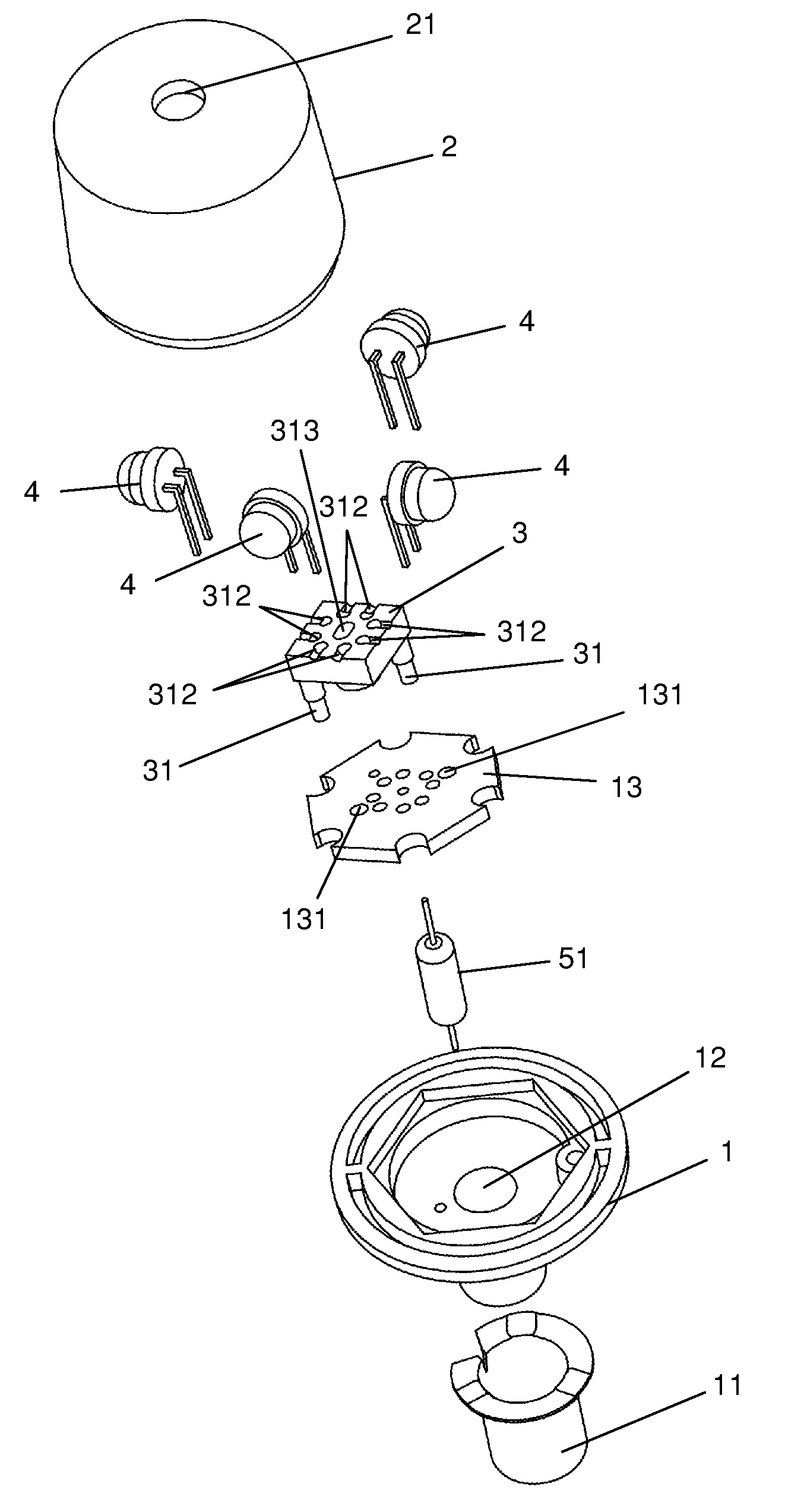
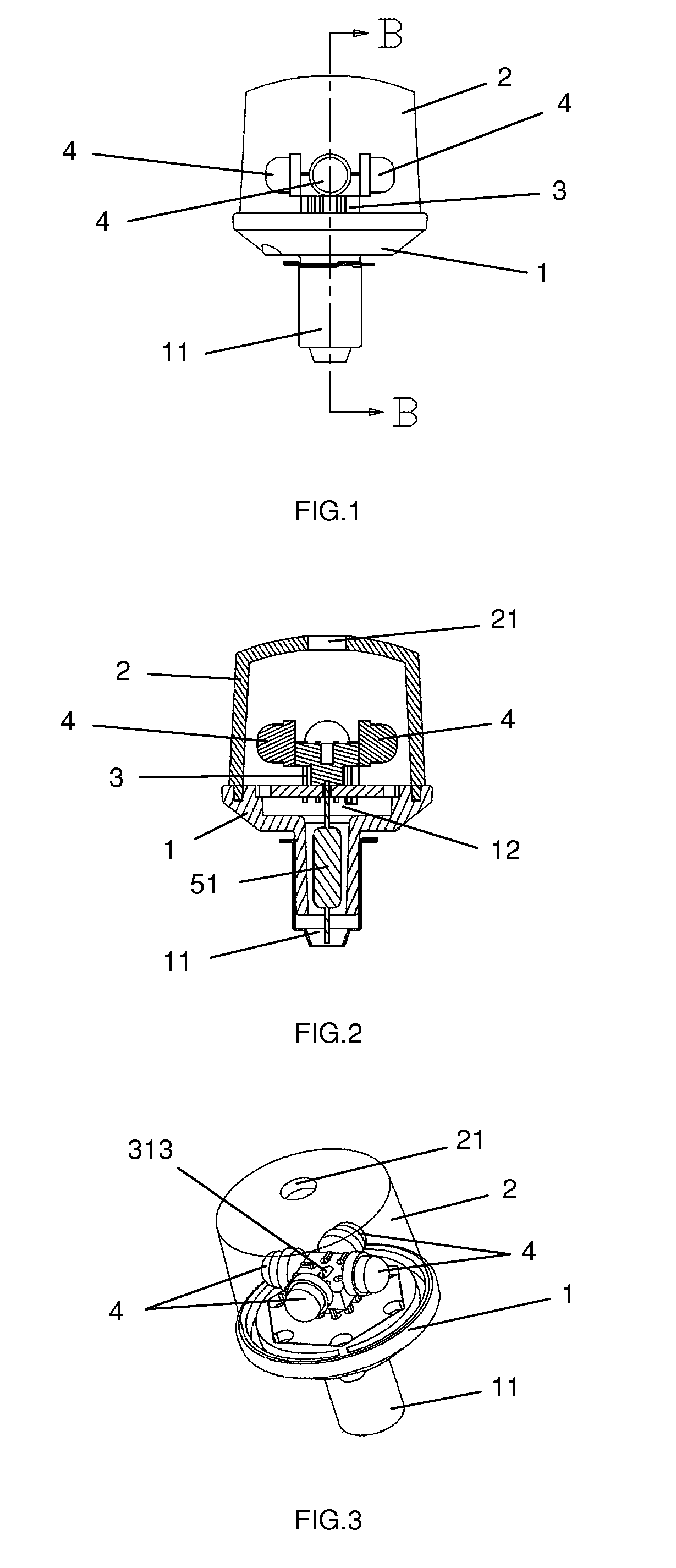
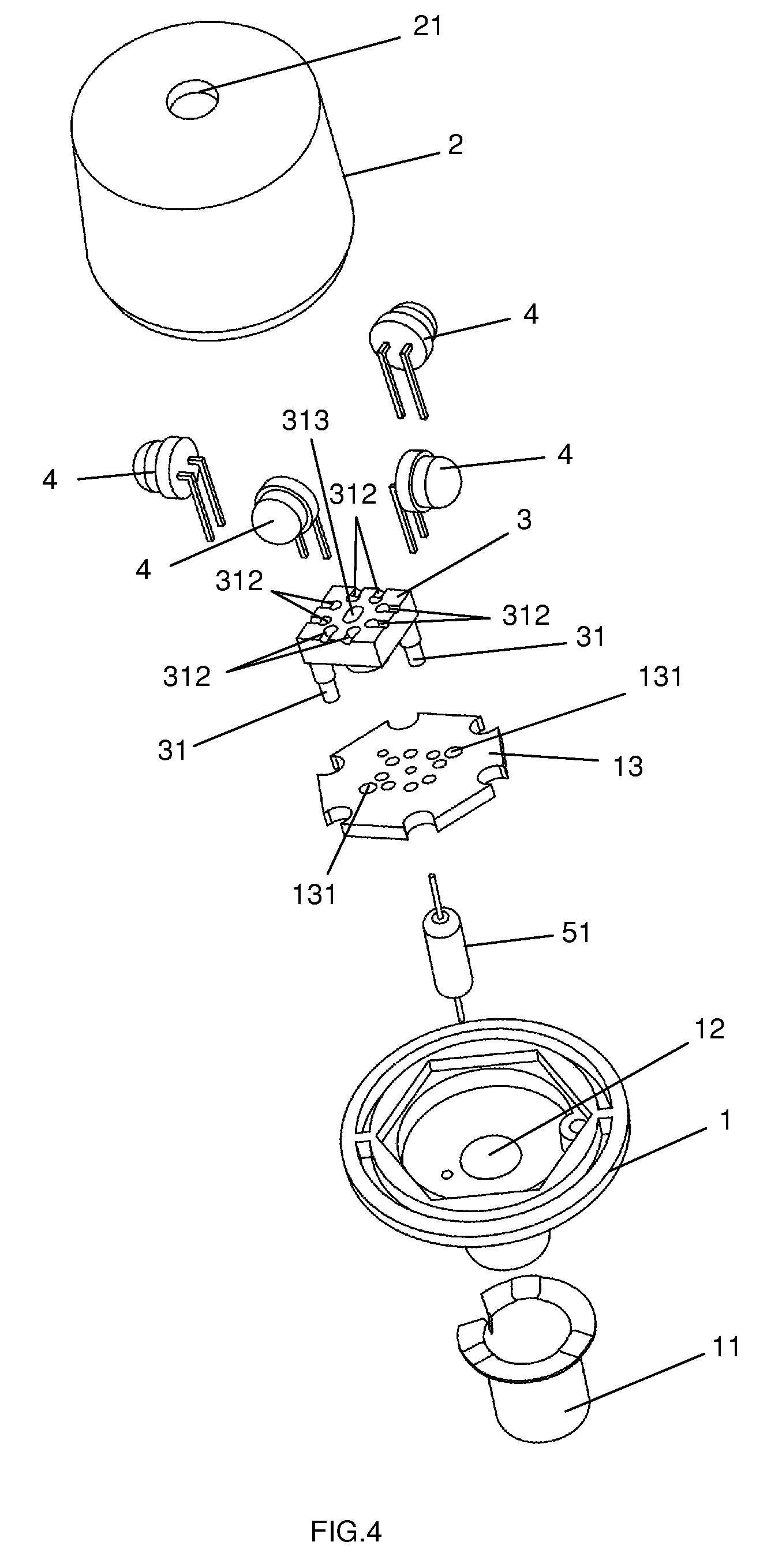
[0044]The preferred embodiments of the present invention are further described in detail with the following embodiments and the accompanying drawings. FIGS. 1 to 6 illustrate the construction of the first embodiment. As shown in FIGS. 1 to 6, the present invention comprises a supporting base 1; a diffusing cover 2 which is a transparent polystyrene cover of matt finishing to filter the light rays it receives, thereby providing even light distribution, in other embodiments, the diffusing cover 2 can be made of other plastic materials and in different colors to provide different moods of lighting, and the diffusing cover 2 has a perforation 21 at its top, the diffusing cover 2 is securely fixed onto the supporting base 1 for safety purpose by thermal compression or in other embodiments, by adhering the diffusing cover 2 onto the supporting base 1. In yet other embodiments, the diffusing cover 2 can be removably engaged with the supporting base 1 by means of engaging flanges for easily...


PUM

PropertyMeasurementUnit
Angleaaaaaaaaaa
Angleaaaaaaaaaa
Coloraaaaaaaaaa

Abstract

A LED light module for portable lighting which comprises a supporting base, a supporting plate, a diffusing cover, an electrical base, an axle, four round flat top single die miniature LEDs each with a light emitting angle of 100 degrees and a driving circuit disposed inside the axle and electrically connected to the LEDs. The present invention is more susceptible of low heat generation and low production costs. Moreover, since only four round flat top single die miniature LEDs are used to provide sufficient light output for an area in 360 degrees, it is more effective than the conventional portable lighting which provide spot lights only.

Description

BACKGROUND OF THE INVENTION[0001]The present invention relates to light modules assembled from light-emitting diodes (“LEDs”) and more particularly pertains to LED light modules for battery operated portable lighting such as flashlights, lanterns, bicycle lights and task lamps.[0002]LEDs are more commonly used in portable lighting than incandescent light bulbs because LEDs use less power, have longer lifetimes, give faster response, produce little heat, endure better vibration and other environmental extremes, and are small in size and light in weight and are thus easier to carry and store.[0003]Advances have been made in improving the light output of LED lighting by making use of an array or even a matrix of LEDs instead of a single LED package. To accommodate more LEDs so as to increase the light output, in some modules the LEDs are mounted on an axle instead of a flat surface. However, existing modules with a plurality of LEDs have the problem that when arranging the LEDs tightly...

Claims


Application Information

Patent Timeline
IPC IPC(8): F21V3/00
CPCF21Y2101/02F21V3/0445F21Y2111/005F21V29/20F21L4/027F21V29/86F21K9/135F21V3/02F21Y2111/007F21V29/506F21V29/83F21V23/003F21K9/232F21Y2115/10F21Y2107/30F21Y2107/40F21Y2107/60F21V23/006F21K9/238F21V29/70F21V3/0625
Inventor YOUNG, TONY CHUNLUNG
Owner CALTRACO INT
Learn More