
Characterization of co-channel interference in a wireless communication system

Active Publication Date: 2010-04-22
TELECOM ITALIA SPA
View PDF13 Cites 15 Cited by
  • Summary
  • Abstract
  • Description
  • Claims
  • Application Information

AI Technical Summary

Benefits of technology

[0012]The objective of the present invention is therefore to provide a methodology which can alleviate at least some of the above cited drawbacks, and in particular which allows interference mitigation to be performed with simple algorithms and light computational load. It also allows reduction in uplink signaling bandwidth.
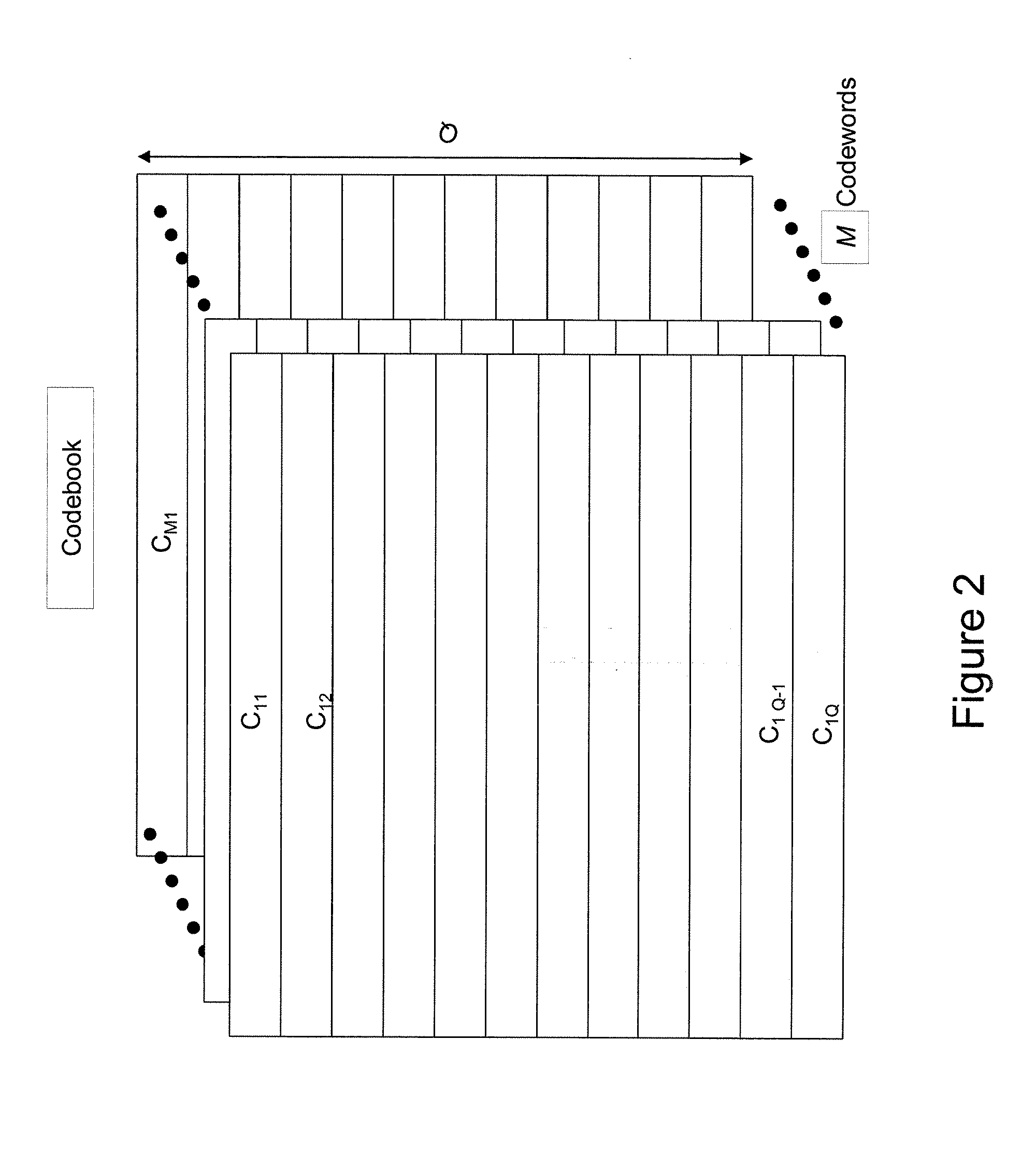
[0017]Preferably, a subset of codewords may be kept invariant in time to minimize the quantization error when new user equipments enter the cell.
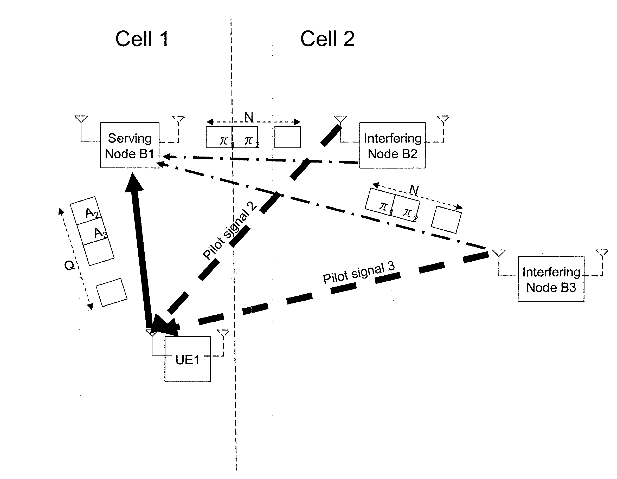
[0019]The present invention can be used advantageously to develop interference control and reduction algorithms based on a good knowledge of the influence that every interfering transceiver station produces on its neighbouring cells. These algorithms should also be conceived to allow messages between different transceiver stations to be exchanged to negotiate a possible reduction of the radiated interference power over any PRBs when needed. The present invention can also be adopted to effectively reduce uplink feedback messages. In particular, vector quantization can be used to perform the so called user equipment grouping. Specifically, when different user equipments send to the respective transceiver station feedback messages that are represented by the same codeword, then these user equipments can be grouped together. Subsequently, and for a predetermined time interval, the transceiver station can request measurement feedback messages from only one or a few of these user equipments acting as a representative sample of the group, instead of the whole group. The user equipments belonging to a given group can also send feedback messages in a round robin fashion until the serving transceiver station estimates that the interference situation sustained by the members of the group diverges.

Problems solved by technology

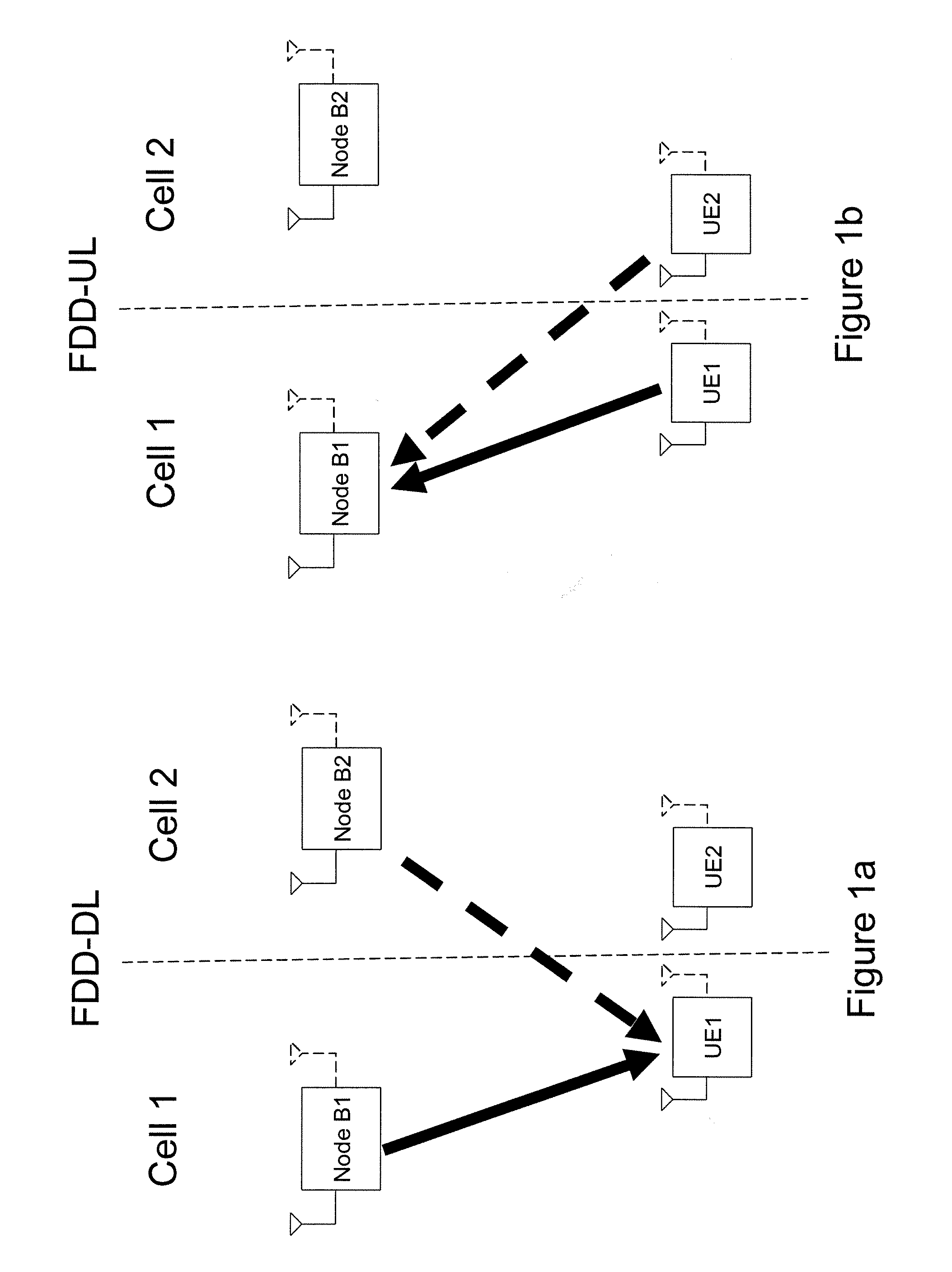
The capability to distinguish which one of the neighbouring cells interference comes from implies that each user equipment should have knowledge of cell-specific training sequences (pilot signal sequences), and the previous step inevitably leads to the use of memory space, computation resources and consequent power consumption in the user equipment;
RRM algorithms attaining global optimization of system throughput via interference control go beyond computation and signaling capability of the system (because of excessive computational and / or signaling load).

Method used


Image

  • Characterization of co-channel interference in a wireless communication system
  • Characterization of co-channel interference in a wireless communication system
  • Characterization of co-channel interference in a wireless communication system

Examples


Embodiment Construction

[0026]The following description is presented to enable a person skilled in the art to make and use the invention. Various modifications to the embodiments will be readily apparent to those skilled in the art, and the generic principles herein may be applied to other embodiments and applications without departing from the spirit and scope of the present invention. Thus, the present invention is not intended to be limited to the embodiments shown, but is to be accorded the widest scope consistent with the principles and features disclosed herein and defined in the attached claims.

[0027]Additionally, in the following, without losing generality, reference will be made to a 3GPP LTE cellular radio communication system, remaining clear that the present invention can also be applied to other type of cellular or non-cellular systems such as WiMAX or WLANs. For this reason, when referring to a transceiver station being part of the network infrastructure, the terminology “Node B”, that is the...


PUM


Abstract

Disclosed herein is a method for characterizing interference in a radio communication system including a plurality of radio transceiver stations configured to communicate with user equipments, the method including: measuring, by a user equipment in radio communication with a serving transceiver station, quantities indicative of interference from interfering transceiver stations; sending the measured quantities to the serving transceiver station; associating at least one codebook with the serving transceiver station, the codebook including a number of codewords each representing a respective quantized interference situation in an area covered by the serving transceiver station; and identifying in the codebook a codeword representative of the quantities measured by the user equipment.

Description

TECHNICAL FIELD OF THE INVENTION[0001]The present invention relates in general to wireless communication systems, and more specifically to co-channel interference characterization, feedback reduction and interference mitigation in cellular and non-cellular radio communication systems.[0002]In particular, cellular radio communication systems where the present invention may find advantageous, but not limitative application, are for example the so-called beyond-3G (3rd Generation) cellular radio communication systems, i.e. new generation cellular radio communication systems having a wider transmission bandwidth than 3G cellular radio communication systems, such as for example those known as Third Generation Partnership Project Long Term Evolution (3GPP LTE) cellular radio communication systems.[0003]Non-cellular radio communication systems where the present invention may find advantageous, but not limitative application are for example Wireless Local Area Networks (WLANs), and in parti...

Claims


Application Information

Patent Timeline
IPC IPC(8): H04L12/26H04B1/38H04B17/00H04W24/00H04W28/04
CPCH04B17/005H04L27/2602H04B17/345H04W28/04H04B17/24H04W24/00H04W28/0236H04W24/08H04W72/0453
Inventor BARBERIS, SERGIO
Owner TELECOM ITALIA SPA
Learn More