Processing apparatus and processing method

a processing apparatus and processing method technology, applied in packaging bottles, transportation and packaging, packaging goods types, etc., can solve the problems of difficult application of techniques to processing apparatuses, adverse effects on tat, and increased oxygen concentration in loading area sb>2/b>,

Active Publication Date: 2010-04-22
TOKYO ELECTRON LTD
View PDF15 Cites 14 Cited by
  • Summary
  • Abstract
  • Description
  • Claims
  • Application Information

AI Technical Summary

Problems solved by technology

However, the above-described thermal processing apparatus is not so resistive to such a differential pressure.
Namely, because of the displacement of the FOUP 3, there may occur mapping error of wafers W and transfer mistake of the wafers W. In addition, the concentration of oxygen in the loading area S2 may be increased by leakage of the nitrogen gas.
In this case, since the atmosphere of the loading area has to be again replaced with nitrogen gas, TAT (Turn Around Time) may be adversely affected.
However, in JP4-6804A, since the container is pressed from above onto the table, it is difficult to apply the technique to a processing apparatus in which a sufficient room is difficult to be obtained above a container.

Method used


Image

  • Processing apparatus and processing method
  • Processing apparatus and processing method
  • Processing apparatus and processing method

Examples


Embodiment Construction

[0032]Embodiments of the present invention will be described in detail below with reference to the drawings.

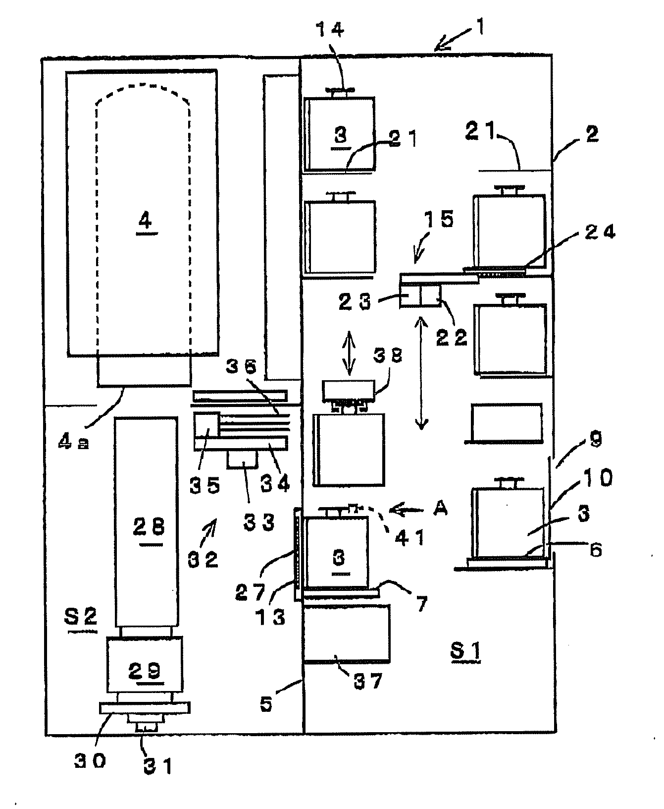
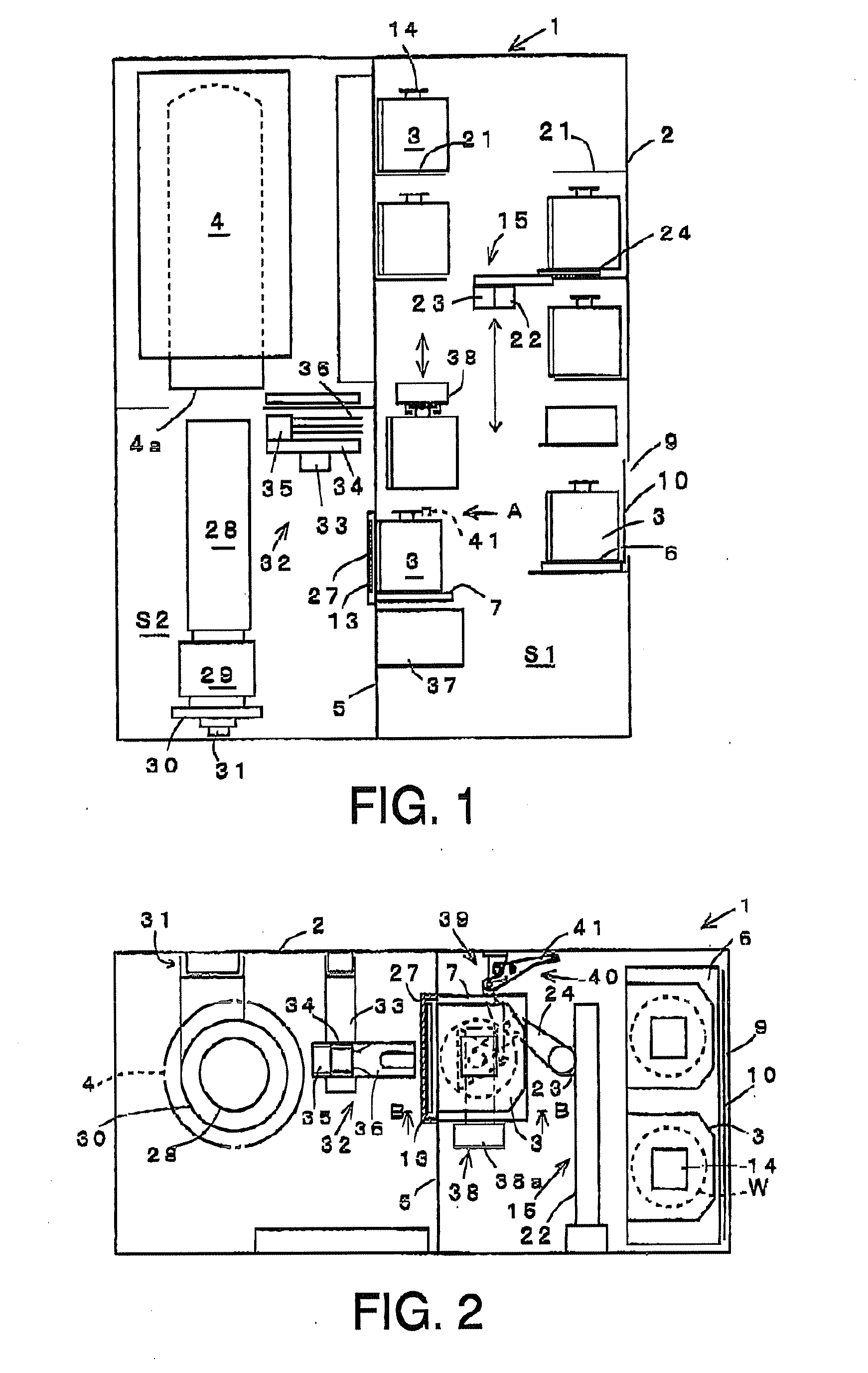
[0033]FIG. 1 is a longitudinal sectional view schematically showing a vertical thermal processing apparatus in one embodiment of a processing apparatus of the present invention. FIG. 2 is a transversal plan view schematically showing the vertical thermal processing apparatus.

[0034]As shown in FIGS. 1 and 2, the vertical thermal processing apparatus (hereinafter referred to also as “thermal processing apparatus”) 1 includes a housing 2 defining an outer profile. In the housing 2, there are formed a carry-in area S1 and a loading area S2. In the carry-in area S1, a FOUP 3 containing wafers W as an object to be processed is carried into and carried out from the thermal processing apparatus 1. In the loading area S2 serving as a conveyance area, the wafers W in the FOUP 3 are conveyed and loaded into a thermal processing furnace 4 which will be described below. The carry-in area S...


PUM


Abstract

A processing apparatus including: a carry-in area into which a container containing substrates to be processed is carried, the container having a flange part on an upper part thereof and an opening in a front surface thereof, with a lid being detachably fixed to the opening; a transfer area whose atmosphere is maintained differently from an atmosphere of the carry-in area; a partition wall separating the carry-in area and transfer area; a through-hole formed in the partition wall; a door configured to open and close the through-hole; and a table on which the container can be placed in the carry-in area. After the container has been placed and then held on the table, the container is brought into contact with the through-hole, the door and the lid are opened, and the substrates to be processed in the container are conveyed to the transfer area so as to process the substrates.

Description

CROSS REFERENCE TO RELATED APPLICATIONS[0001]This application is based upon and claims the benefit of priority from the prior Japanese Patent Application No. 2008-267584 filed on Oct. 16, 2008, the entire contents of which are incorporated herein by reference.FIELD OF THE INVENTION[0002]The present invention relates to a processing apparatus and a processing method in which a substrate to be processed is taken out from a container, which has an opening in a front surface thereof with a lid, and the substrate to be processed is subjected to a predetermined process such as a thermal process.BACKGROUND ART [0003]As one of semiconductor manufacturing apparatuses, there has been known a thermal processing apparatus that performs a thermal process such as a CVD (Chemical Vapor Deposition) process to a number of substrates to be processed such as semiconductor wafers (hereinafter referred to also as “wafer”). The thermal processing apparatus includes a carry-in area into which a container ...

Claims


Application Information

Patent Timeline
Patent Type & Authority Applications(United States)
IPC IPC(8): H01L21/68
CPCH01L21/67775H01L21/67772
Inventor HISHIYA, KATSUYUKI
Owner TOKYO ELECTRON LTD
Why Eureka
Try Eureka