
Anchor device with double-sectioned head and method of using the same

a technology of anchor device and head, which is applied in the direction of threaded fasteners, screws, building repairs, etc., can solve the problems of time-consuming process and complicating assembly line fabrication of finished articles, and achieve the effect of reducing corrosion of the anchor devi

Active Publication Date: 2010-04-29
AVK INDAL PRODS
View PDF21 Cites 3 Cited by
  • Summary
  • Abstract
  • Description
  • Claims
  • Application Information

AI Technical Summary

Benefits of technology

[0005]A particular application for which species of the disclosed invention may be utilized is for attaching components of a roof rack, typically the rails, or similar apparatus to the sheet metal top of a vehicle, such as an automobile. For the known method of installing the rails of a roof rack of an automobile, an opening is placed in the material of the vehicle roof by drilling or punching, and a threaded anchor device is installed within the resulting hole. The anchor device is thereafter installed by application of an axial force by reciprocation or rotation of a stud attached to a portion of the anchor device. The application of axial force causes a portion of the sleeve section of the anchor to deform into a bubble on the second side of the work piece, such that the thin wall of the work piece is sandwiched on the second side by the bubble and by the head of the anchor device on the first side, thereby preventing the withdrawal of the anchor from the work piece.
[0008]Embodiments of the disclosed anchor device may include a deformable seal member, which seal member is adjacent to a shoulder formed by the terminus of the lower head of the device, wherein during installation the seal member deforms and is held between the work piece and the shoulder, thus creating a seal between the anchor device and the exterior surface of the work piece. In the case of a roof rack, the seal member prevents or restricts moisture from penetrating into the hole into which the sleeve member of the anchor device has expanded, thereby reducing corrosion of the anchor device and in the roof of the vehicle.

Problems solved by technology

Second, the structure is attached to the work piece, typically by threaded fasteners which are made up into threads in the anchor.
However, this process can be time consuming, can complicate assembly line fabrication of the completed article, and requires a separate fastener for each anchor.

Method used


Image

  • Anchor device with double-sectioned head and method of using the same
  • Anchor device with double-sectioned head and method of using the same
  • Anchor device with double-sectioned head and method of using the same

Examples


Embodiment Construction

[0016]It is to be appreciated that the dimensions, materials, finishes, etc., called out within the drawings are for specific species of the device, and are provided by way of example only. Embodiments of the invention are not limited to the dimensions, materials, finishes or other detail set forth within the drawings.

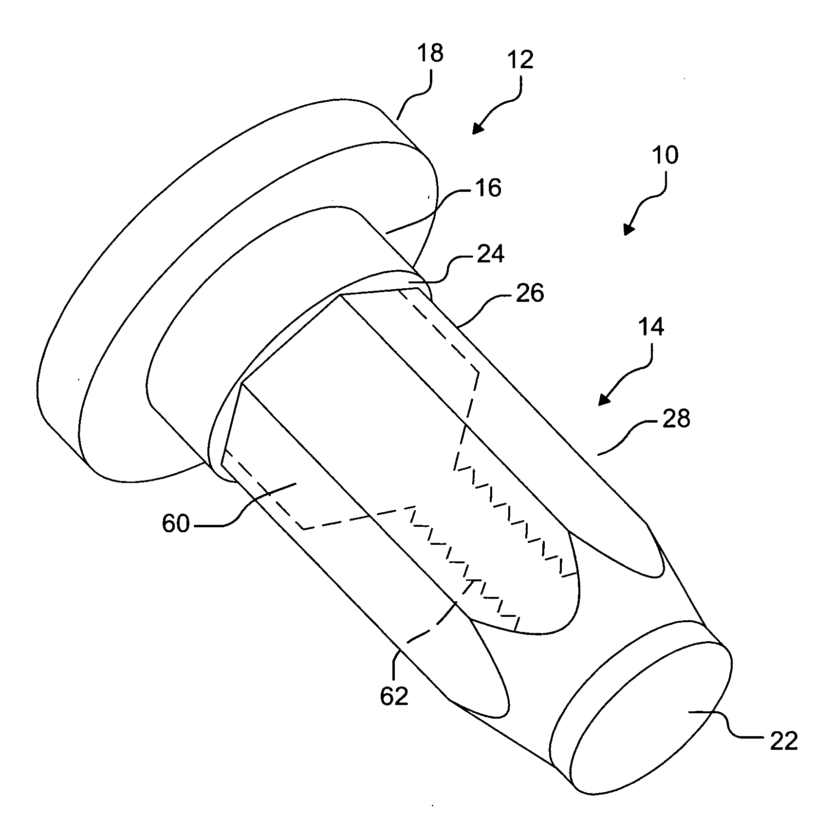
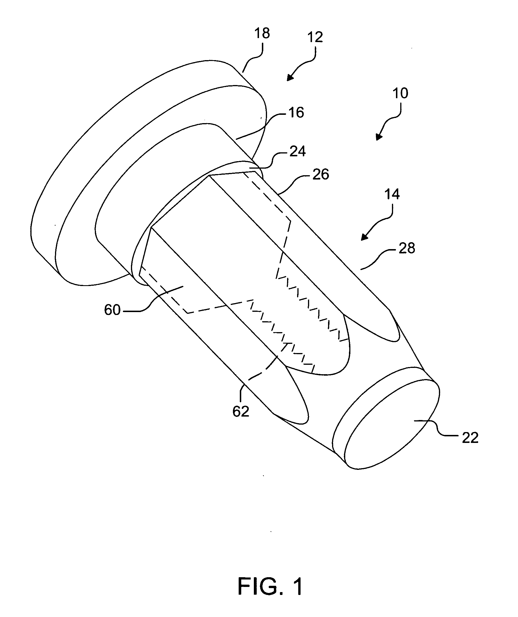
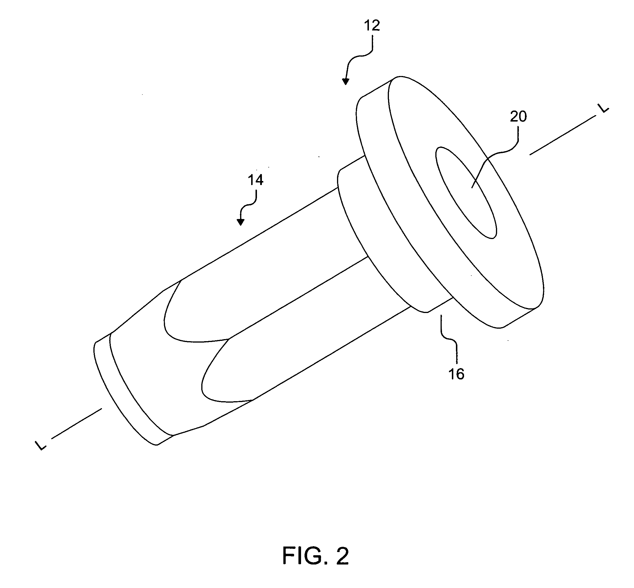
[0017]Referring now to the figures, FIG. 1 shows an isometric view of embodiment of the disclosed anchor device 10 in an uninstalled condition. It is to be appreciated that the disclosed anchor device 10 may be manufactured from carbon steel and various alloys in a cold-headed extrusion process, with no machining required.

[0018]Anchor device 10 comprises a double sectioned head member 12 and a sleeve section 14. Double-sectioned head member 12 distinguishes the present invention from other anchor devices in that double-sectioned head member 12 comprises a lower head member 16 which depends from upper head member 18. This configuration allows upper head member 18 to ext...


PUM


Abstract

A modified anchor device for attaching a structure to a thin-walled work piece allows a structure, such as a luggage or utility rack, to be attached to a work piece, such as an automobile roof, without threaded fasteners connecting the structure to the work piece. The anchor device has an double-sectioned head having an upper head member and a lower head member The upper head member extends above the surface of the work piece a sufficient distance such that the upper head member engages the top surface of the structure, thus retaining the bottom side of the structure in face-to-face contact with the top side of the work piece.

Description

CROSS-REFERENCE TO RELATED APPLICATION[0001]U.S. Provisional Application No. 61 / 197,215 for this invention was filed on Oct. 23, 2008 for which these inventors claim domestic priority.BACKGROUND OF THE INVENTION[0002]The disclosed device relates generally to thin wall anchor devices, specifically threaded inserts and rivnuts (collectively “anchor devices”). The present device comprises an anchor device comprising a double sectioned head member, the head member comprising an upper head member which extends above the surface of a work piece. The upper head member is used to attach a structure to the work piece, where the upper head member is received by a slot or aperture of the structure, to make the attachment. The use of the present device may eliminate or reduce the need for separate fasteners to secure the structure to the work piece and may expedite the attachment of the structure to the work piece. In one embodiment, the anchor has a smooth bore and may be installed by means of...

Claims


Application Information

Patent Timeline
IPC IPC(8): E04B1/38F16B13/04
CPCF16B19/1072F16B37/067F16B21/09
Inventor MCGEE, THOMASNERI, FRANK
Owner AVK INDAL PRODS
Learn More