Organic light emitting display device

a light-emitting display and organic technology, applied in the direction of discharge tube luminescnet screens, discharge tube/lamp details, electric discharge lamps, etc., can solve the problems of increased power consumption, uniform picture quality, deterioration of picture quality, etc., to achieve high-definition picture quality, reduce power consumption, and reduce the difference in brightness between pixels

Inactive Publication Date: 2010-04-29
SAMSUNG MOBILE DISPLAY CO LTD
View PDF5 Cites 20 Cited by
  • Summary
  • Abstract
  • Description
  • Claims
  • Application Information

AI Technical Summary

Benefits of technology

[0008]It is an aspect of the present invention to provide an organic light emitting display device capable of minimizing or reducing a voltage difference between different locations on a cathode electrode.
[0012]With the organic light emitting display device according to the embodiments of the present invention, the spacers and the auxiliary electrode in a stacked structure may be formed on the sealing substrate, and the auxiliary electrode may be closely adhered to the cathode electrode by the spacers. The voltage across the cathode electrode may be substantially constantly maintained by the auxiliary electrode having lower resistance than that of the cathode electrode irrespective of its location, such that power consumption may be decreased, and difference in brightness between pixels may be reduced. The auxiliary electrode may contact the cathode electrode stably by using the spacers, making it possible to implement high definition picture quality. Also, the auxiliary electrode of the embodiments of the present invention may be formed of metal having low transmittance to function as a black matrix for suppressing reflection of external light, thereby decreasing black brightness and improving contrast. As such, a separate black matrix or polarizing plate may not be required, thereby simplifying a structure of a display device.

Problems solved by technology

However, since the transparent electrode material has high resistivity, when the cathode electrode is formed as a common electrode over the display region, a voltage difference occurs between different locations across the cathode electrode, causing a problem that picture quality is not uniform.
In other words, difference in brightness occurs due to the voltage difference between a position close to the power supply source and a position far from the power supply source, thereby causing the deterioration in the picture quality.
However, if the driving voltage is increased, it causes an increase in power consumption.

Method used


Image

  • Organic light emitting display device
  • Organic light emitting display device
  • Organic light emitting display device

Examples


Embodiment Construction

[0020]In the following detailed description, only certain exemplary embodiments of the present invention have been shown and described, simply by way of illustration. As those skilled in the art would realize, the described embodiments may be modified in various different ways, all without departing from the spirit or scope of the present invention. Accordingly, the drawings and description are to be regarded as illustrative in nature and not restrictive. In addition, when an element is referred to as being “on” another element, it can be directly on another element or be indirectly on another element with one or more intervening elements interposed therebetween. Also, when an element is referred to as being “connected to” another element, it can be directly connected to another element or be indirectly connected to another element with one or more intervening elements interposed therebetween. Hereinafter, like reference numerals refer to like elements.

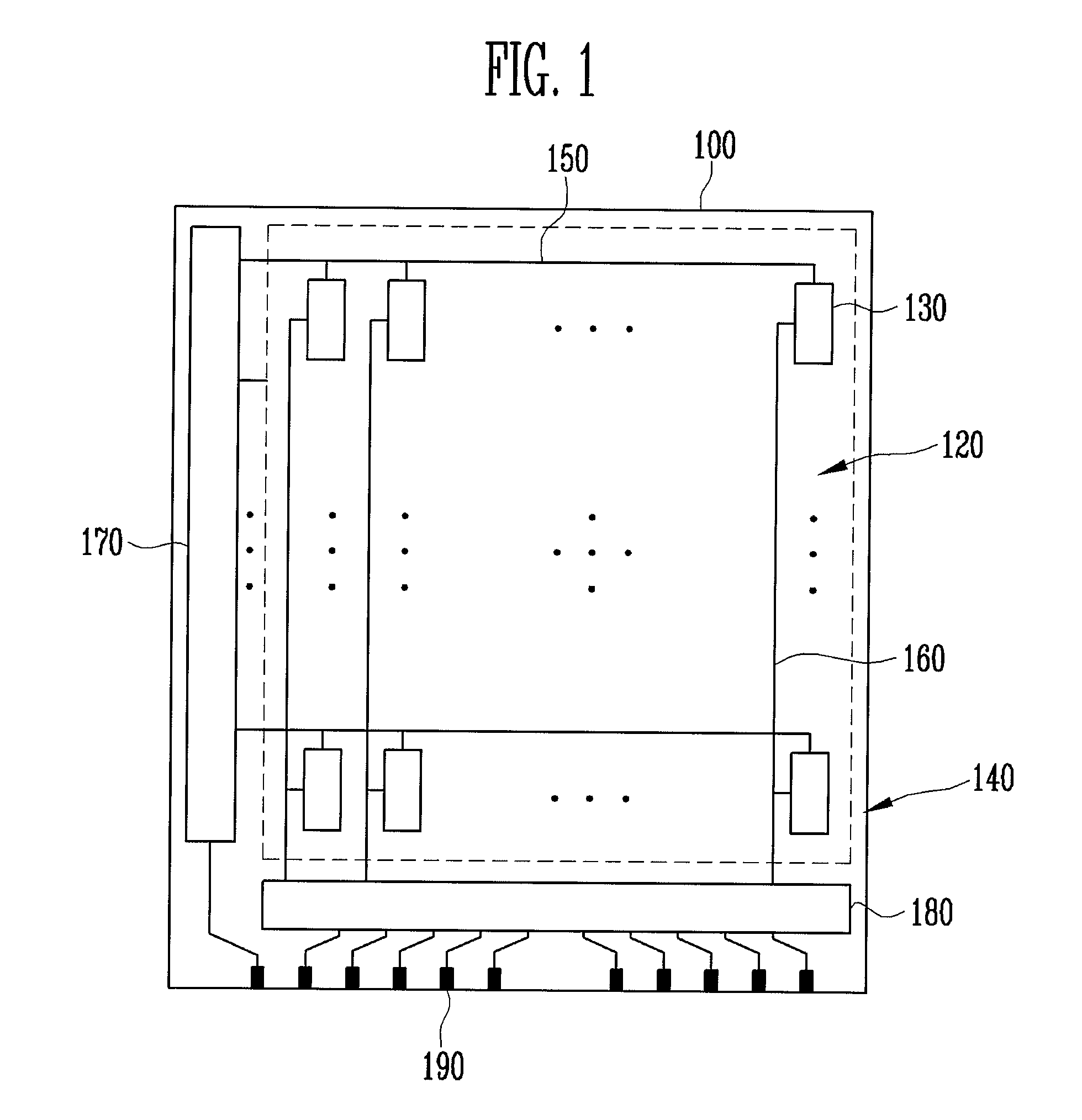
[0021]FIG. 1 is a schematic dr...


PUM


Abstract

Embodiments of the present invention provide an organic light emitting display device including: a plurality of light emitting elements on a first substrate, each of the plurality of light emitting elements including a first electrode and an organic light emitting layer, and a second electrode on the plurality of light emitting elements; a second substrate facing the first substrate with the plurality of light emitting elements therebetween; spacers on the second substrate corresponding to portions of the second electrode, the portions located on spaces between the plurality of light emitting elements; and an auxiliary electrode on the spacers and contacting the second electrode.

Description

CROSS-REFERENCE TO RELATED APPLICATIONS[0001]This application claims priority to and the benefit of Korean Patent Application No. 10-2008-0106359, filed on Oct. 29, 2008, in the Korean Intellectual Property Office, the entire content of which is incorporated herein by reference.BACKGROUND OF THE INVENTION[0002]1. Field of the Invention[0003]The present invention relates to an organic light emitting display device having a front emitting structure, and more particularly to an organic light emitting display device having a cathode electrode shared by a plurality of light emitting devices in a display region.[0004]2. Description of Related Art[0005]An organic light emitting display device, which is a display device having self-light emitting characteristics, includes a substrate arranged with light emitting elements each including an organic light emitting layer, a sealing substrate disposed to facing the substrate, and a sealant sealing the light emitting elements between the substrat...

Claims


Application Information

Patent Timeline
Patent Type & Authority Applications(United States)
IPC IPC(8): H01J1/63
CPCH01L27/3244H01L51/5237H01L51/5203H10K59/12H10K50/824H10K50/8428H10K50/865H01L23/293H01L31/0264H01L2924/01024H10K50/805H10K50/84
Inventor SEO, CHANG-SUKIM, TAE-GONKOH, SUNG-SOOJEON, HEE-CHULHAN, BYUNG-UK
Owner SAMSUNG MOBILE DISPLAY CO LTD
Why Eureka
Try Eureka