Electronic ballast

a technology of electronic ballast and ballast body, which is applied in the direction of electric variable regulation, process and machine control, instruments, etc., can solve the problems of inability to control power, electronic ballast may not save power of a product, and the disadvantages of electronic ballast must be solved, so as to save energy and easily and conveniently control the consumption of power

Inactive Publication Date: 2010-04-29
FEELUX CO LTD
View PDF11 Cites 5 Cited by
  • Summary
  • Abstract
  • Description
  • Claims
  • Application Information

AI Technical Summary

Benefits of technology

[0010]As described above, an electronic ballast may minimize a reduction in energy efficiency caused by loss of heat and loss of power caused by a decrease in a power factor, compared to a magnetic ballast. Thus, the electronic ballast may efficiently save power. However, the electronic ballast generates constant power and thus cannot control power varying according to a selection of a user. Thus, the electronic ballast may not save power of a product in which the electronic ballast is installed. As a result, these disadvantages of the electronic ballast are required to be solved.
[0011]Accordingly, in order to solve the above problems, the present invention provides an electronic ballast for varying an inductor or a capacitor of a resonant circuit according to a selection of a user to adjust consumed power of a lamp so as to more efficiently control a power saving effect.
[0015]According to another aspect of the present invention, there is provided an electronic ballast including: a rectifier which rectifies AC power into DC power; a power factor compensator which improves a power face of the DC power; an inverter which inverts the DC current into high frequency square wave power; and a resonant circuit which receives the high frequency square wave power from the inverter, adjusts impedance, transforms the high frequency square wave power into high frequency sine wave power, and outputs the high frequency sine wave power.
[0023]As described above, an electronic ballast according to the present invention can vary an inductor or a capacitor of a resonant circuit according to a selection of a user to adjust consumed power of a lamp according to the selection of the user so as to save energy. Also, the user can further easily and conveniently control the consumed power through a switch control which is positioned outside a fluorescent lamp case.

Problems solved by technology

However, the electronic ballast generates constant power and thus cannot control power varying according to a selection of a user.
Thus, the electronic ballast may not save power of a product in which the electronic ballast is installed.
As a result, these disadvantages of the electronic ballast are required to be solved.

Method used


Image

  • Electronic ballast
  • Electronic ballast
  • Electronic ballast

Examples


Embodiment Construction

[0032]The present invention will now be described more fully with reference to the accompanying drawings, in which exemplary embodiments of the invention are shown. In the drawings, the thicknesses of lines or the sizes of elements are exaggerated for clarity. Also, since later-described terms are defined in consideration of the functions of the present invention, they may vary according to users' intentions or practice. Hence, the terms must be interpreted based on the contents of the entire specification.

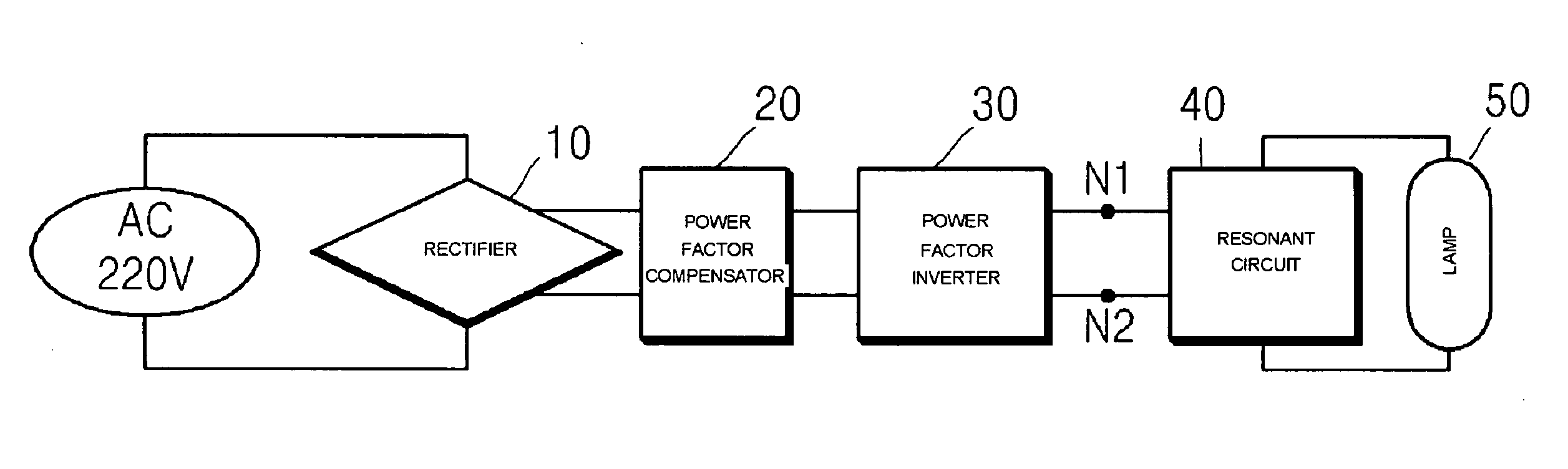
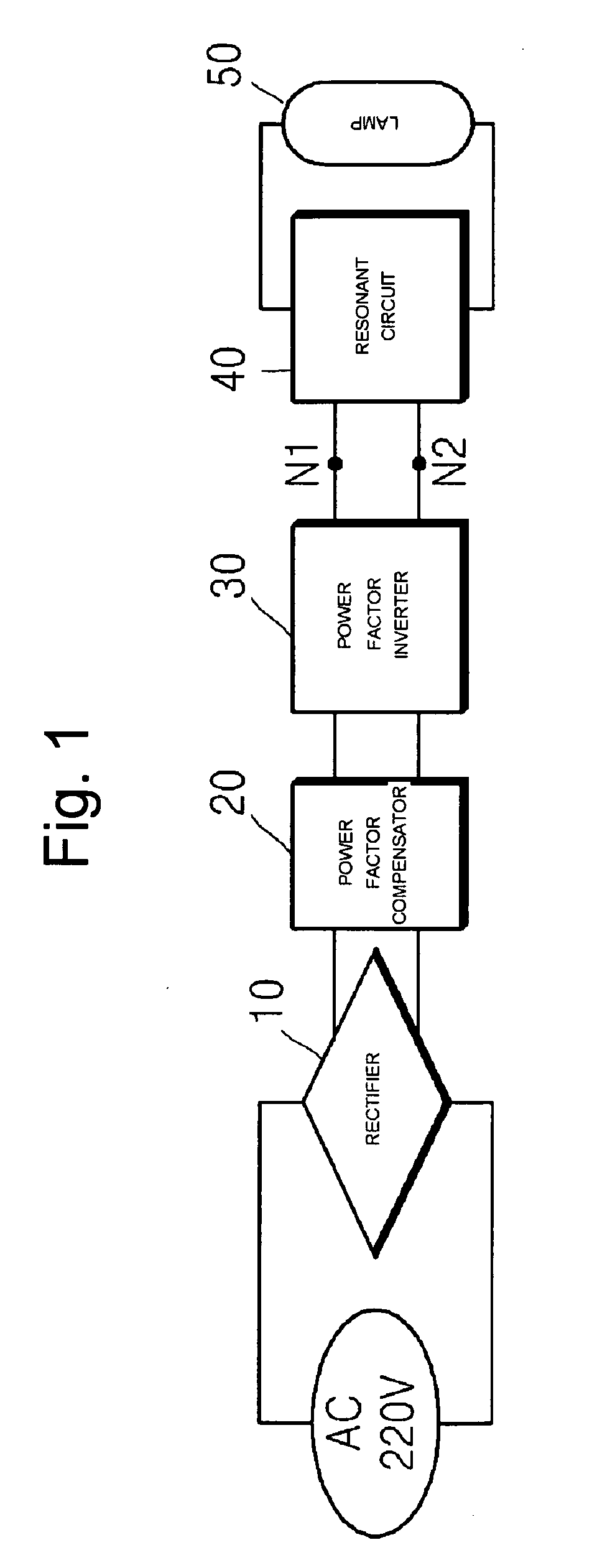
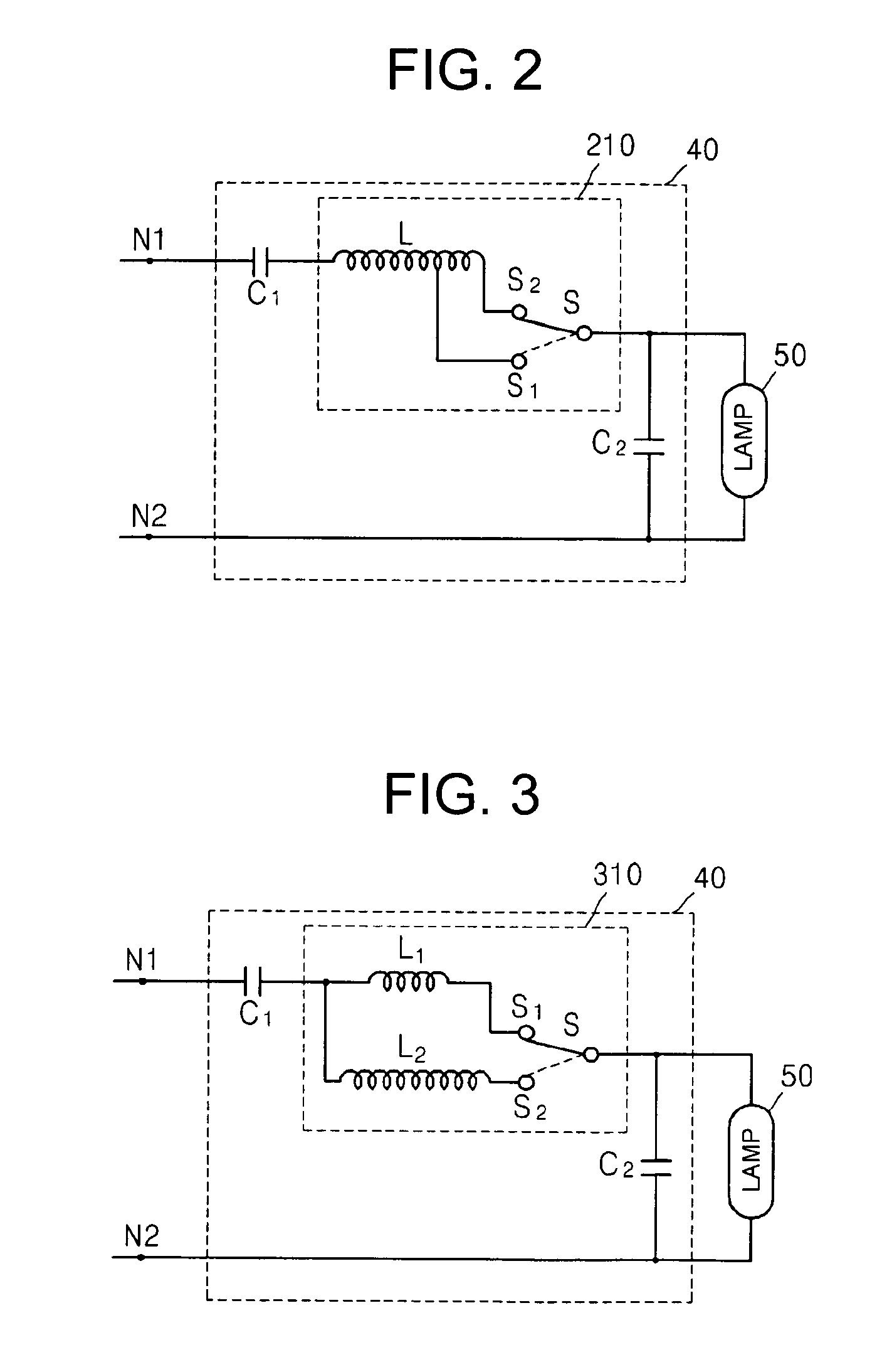
[0033]FIG. 1 is a schematic block diagram of an electronic ballast according to an embodiment of the present invention. Referring to FIG. 1, the electronic ballast includes a rectifier 10, a power factor compensator 20, an inverter 30, a resonant circuit 40, and a lamp 50.

[0034]An operation of the electronic ballast of the present embodiment will now be described in detail.

[0035]The rectifier 10 receives alternating current (AC) power from an external source and rectifies the AC p...


PUM


Abstract

Provided is an electronic ballast including: a rectifier which rectifies alternating current (AC) power into direct current (DC) power; a power factor compensator which improves a power face of the DC power; an inverter which inverts the DC current into high frequency square wave power; and a resonant circuit which receives the high frequency square wave power from the inverter, adjusts impedance, transforms the high frequency square wave power into high frequency sine wave power, and outputs the high frequency sine wave power.

Description

CROSS-REFERENCE TO RELATED PATENT APPLICATION[0001]This application claims the benefit of Korean Patent Application No. 10-2008-0104724, filed on Oct. 24, 2008, in the Korean Intellectual Property Office, the disclosure of which is incorporated herein in its entirety by reference.BACKGROUND OF THE INVENTION[0002]1. Field of the Invention[0003]The present invention relates to an electronic ballast, and more particularly, to an electronic ballast for varying an inductor or a capacitor of a resonance circuit according to a selection of a user in order to adjust consumed power of a lamp.[0004]2. Description of the Related Art[0005]A fluorescent lamp is a kind of discharge tubes and requires a high voltage on an initial stage to discharge thermal electrons necessary for electric discharge. Also, the fluorescent lamp has a negative resistance characteristic in which a voltage applied thereto after the electric discharge decreases with an increase in a current flowing in the fluorescent la...

Claims


Application Information

Patent Timeline
Patent Type & Authority Applications(United States)
IPC IPC(8): H05B41/26
CPCH05B41/2885Y02B20/202H05B41/42Y02B20/00H05B41/14
Inventor PARK, HYUN JOOCHOI, WOO SUNG
Owner FEELUX CO LTD
Why Eureka
Try Eureka