System and method for monitoring vibration of power transformer

a technology of power transformer and monitoring system, which is applied in the direction of vibration measurement in solids, material analysis using wave/particle radiation, instruments, etc., can solve the problems of frequent power outage, unmonitored vibration of the outer case of the transformer or its associated components caused by resonance, and interruption in the supply of electricity, so as to reduce the probability of transformer failure and unscheduled downtime

Inactive Publication Date: 2010-04-29
KOREA ELECTRIC POWER CORP
View PDF11 Cites 17 Cited by
  • Summary
  • Abstract
  • Description
  • Claims
  • Application Information

AI Technical Summary

Benefits of technology

[0008]With the foregoing drawbacks in mind, it is therefore an object of the invention to provide a system for monitoring the vibration of a power transformer that ca

Problems solved by technology

Since a transformer failure brings a catastrophic accident or damages, the transformer needs continuous inspection and pre-remedial measure during its manufacturing process as well as installing or operating stages thereof.
Meanwhile, an interruption in the supply of electricity, i.e., power outage is frequently reported.
Most of such power outages are attributed to the transformer failure which is caused by electrical or mechanical defect.
However, the mechanical defect, e.g., vibration of the outer case of the transformer or its associated components caused by resonance seems not to be continuously monitored during the operation.
Particularly, considering the operational features of a large-sized transformer installed at a power plant, it can be noted that most of the accidents other than an abrupt failure, e.g., earth faults occur when trivial defects at issue have been accumulated for a long period of time.
Recently, there have been frequent reports about a catastro

Method used


Image

  • System and method for monitoring vibration of power transformer
  • System and method for monitoring vibration of power transformer
  • System and method for monitoring vibration of power transformer

Examples


Embodiment Construction

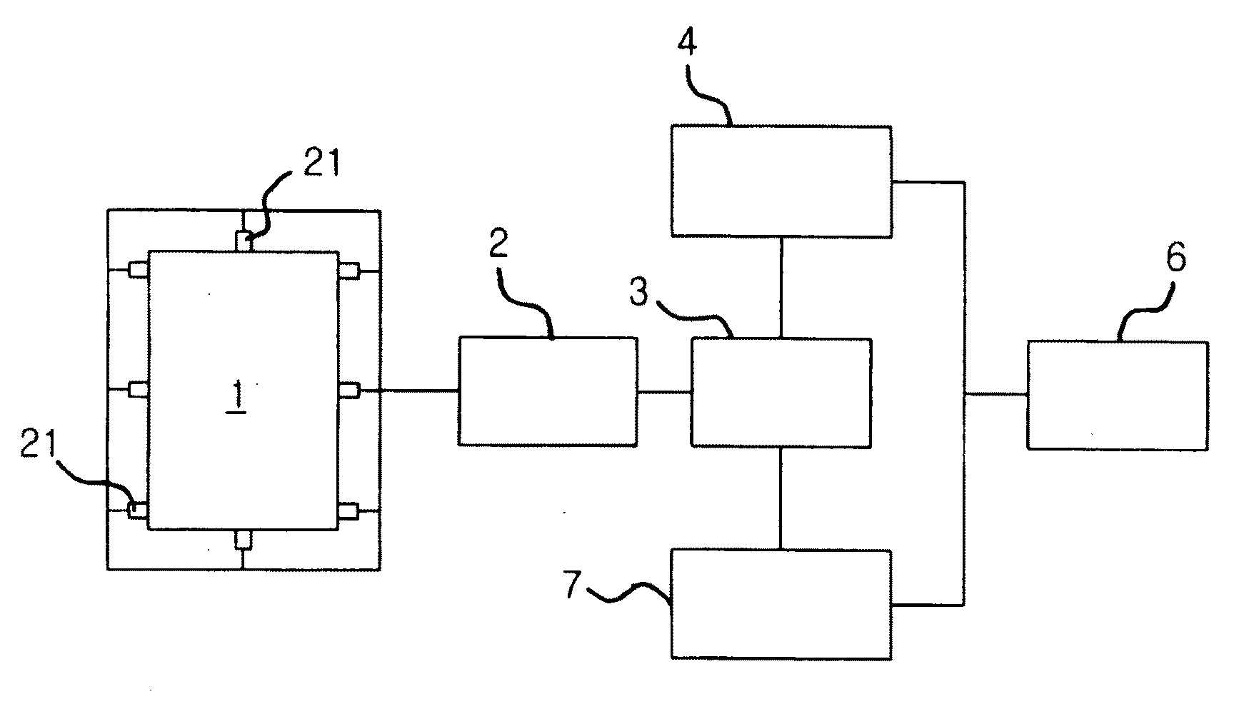
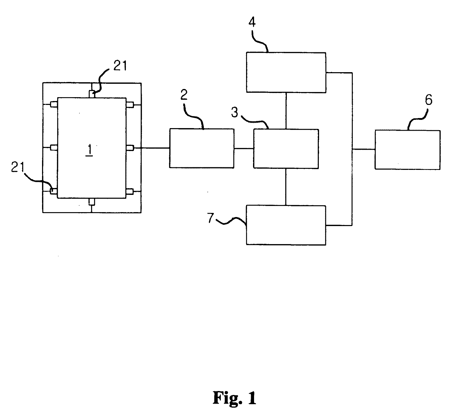
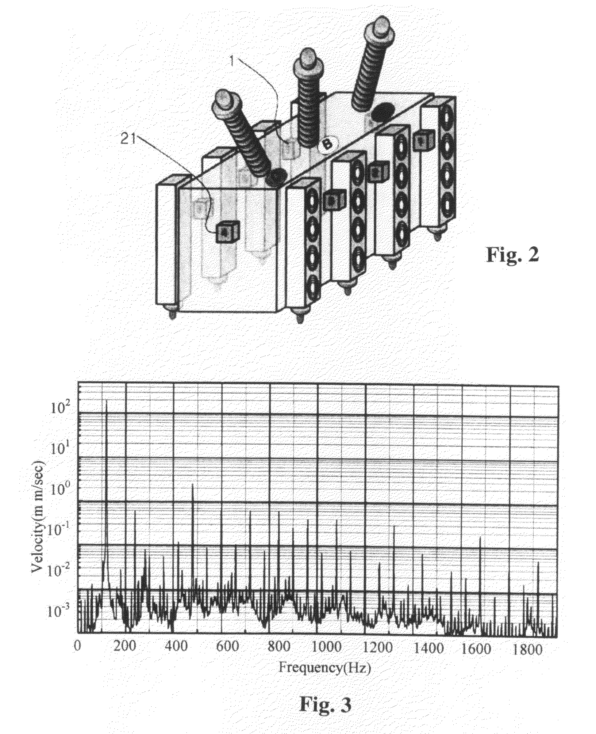
[0022]The other objects, features, advantages of the invention will become apparent from a review of the following detailed description of the preferred embodiment taken in conjunction with the accompanying drawings. FIG. 1 is a view schematically illustrating the construction of a system for monitoring the vibration of a power transformer in accordance with the invention. Referring to FIG. 1, the system for monitoring the vibration of the power transformer in the preferred embodiment of the present invention comprises a transformer body 1 having a vibration sensor 21, e.g., accelerometer mounted thereon, a control panel 2, a database 3, a monitoring system 4, an expert system 7 and an operator's personal computer 6. FIG. 2 is a partial perspective view showing that at least one vibration sensor 21 is mounted on the predetermined location on the outer case of the transformer body 1. The number of the vibration sensors to be attached and their locations are empirically determined aft...


PUM


Abstract

The present invention provides a system and method for monitoring vibration of a power transformer. The system comprises at least one vibration sensor operably mounted to the outer case of a transformer for sensing vibration of the power transformer; a spectrum analyzer for processing the vibration signal from the vibration sensor, the spectrum analyzer generating a frequency spectrum of the vibration signal and calculating a velocity rating from the frequency spectrum; a diagnosing means for evaluating the velocity rating of the vibration signal, the diagnosing means assigning a vibration grade for each velocity rating, the diagnosing means finding the maximum velocity rating; and a means for dispatching a control message to an operator when the maximum velocity rating reaches a threshold value. It can be appreciated that the mechanical health of a large-sized transformer can be managed in a systematic and efficient manner during its operation. This system can prevent accidents due to the mechanical failure of the transformer or diagnosing failure of the transformer itself during its operation. This system also can provide useful information to determine when the transformer has to be replaced and further to predict what the expected lifespan of the transformer will be.

Description

BACKGROUND OF THE INVENTION[0001]1. Field of the Invention[0002]The present invention relates generally to a system and method for monitoring vibration of a power transformer, and more specifically, to a system and method for monitoring vibration of a power transformer capable of analyzing the vibration of the power transformer on a real time basis to systematically manage the mechanical health of the power transformer.[0003]2. Description of the Related Art[0004]Generally, a power transformer is important equipment used for supplying electric power at a power plant, electric power transforming or transmitting station. The power transformer requires a high reliability in its operation and continuous maintenance thereof. Since a transformer failure brings a catastrophic accident or damages, the transformer needs continuous inspection and pre-remedial measure during its manufacturing process as well as installing or operating stages thereof.[0005]Various monitoring systems for analyzi...

Claims


Application Information

Patent Timeline
IPC IPC(8): G08B21/18G01M7/00
CPCG01H1/003G01M99/00
Inventor LEE, WOOK RYUNLEE, JUN SHINBAE, YONG CHAEKIM, BYONG HANLEE, SANG KIL
Owner KOREA ELECTRIC POWER CORP
Why Eureka
Try Eureka