Measurement of functional microcirculatory geometry and velocity distributions using automated image analysis

Active Publication Date: 2010-04-29
MVM
View PDF1 Cites 51 Cited by
  • Summary
  • Abstract
  • Description
  • Claims
  • Application Information

AI Technical Summary

Benefits of technology

[0006]An object of the present invention is to provide a method of analyzing microvasculatory video

Problems solved by technology

The microscope-based configuration, however, makes capillaroscopy systems inaccessible to deep-lying tissue.
Although the program is

Method used


Image

  • Measurement of functional microcirculatory geometry and velocity distributions using automated image analysis
  • Measurement of functional microcirculatory geometry and velocity distributions using automated image analysis
  • Measurement of functional microcirculatory geometry and velocity distributions using automated image analysis

Examples


Embodiment Construction

[0050]With currently available imaging techniques, such as capillaroscopy, OPS or SDF imaging, “vessels” are only observed in the presence of red blood cells that contain hemoglobin, which highly absorbs the incident wavelength in contrast to the background medium. The capillary vessels themselves are basically invisible to these imaging techniques in the absence of red blood cells. Videos of the microcirculation merely show plugs of red blood cells that are delineated by the vessel wall and are therefore referred to as “vessels”.

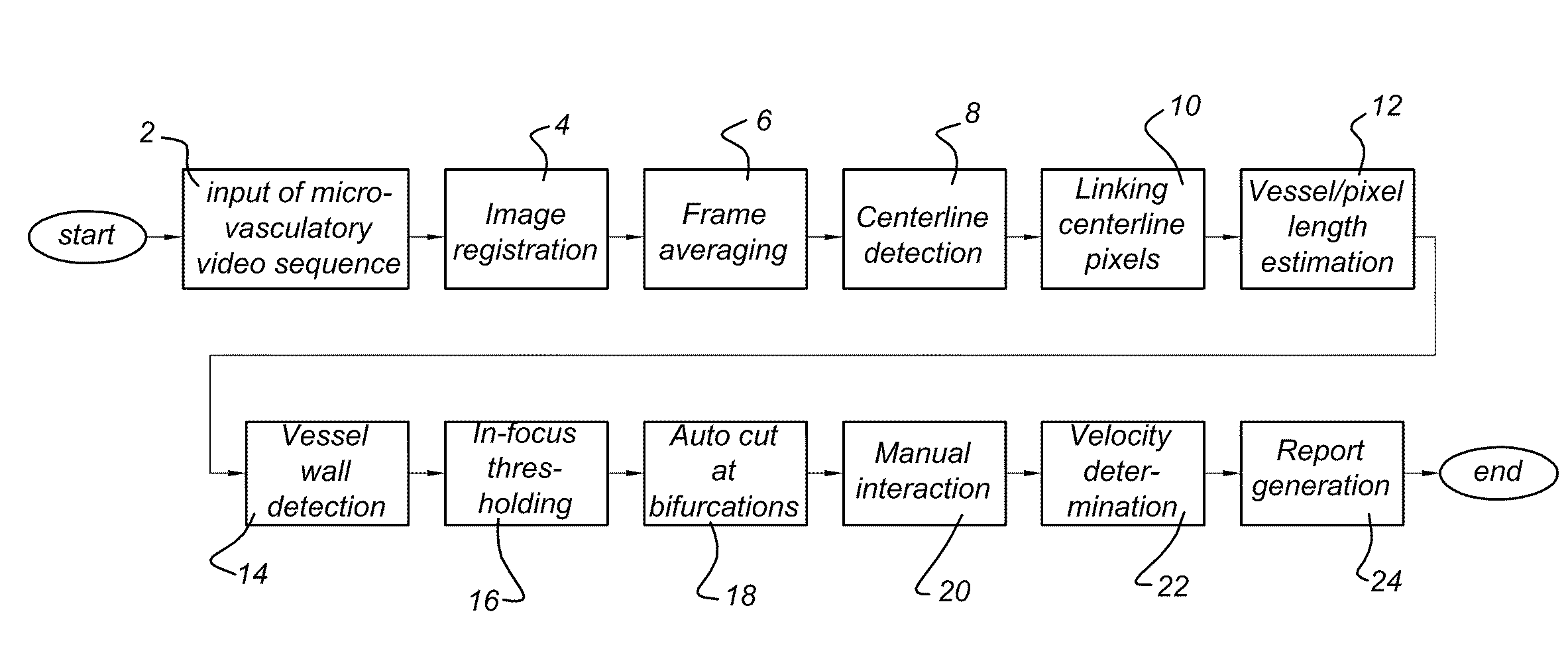
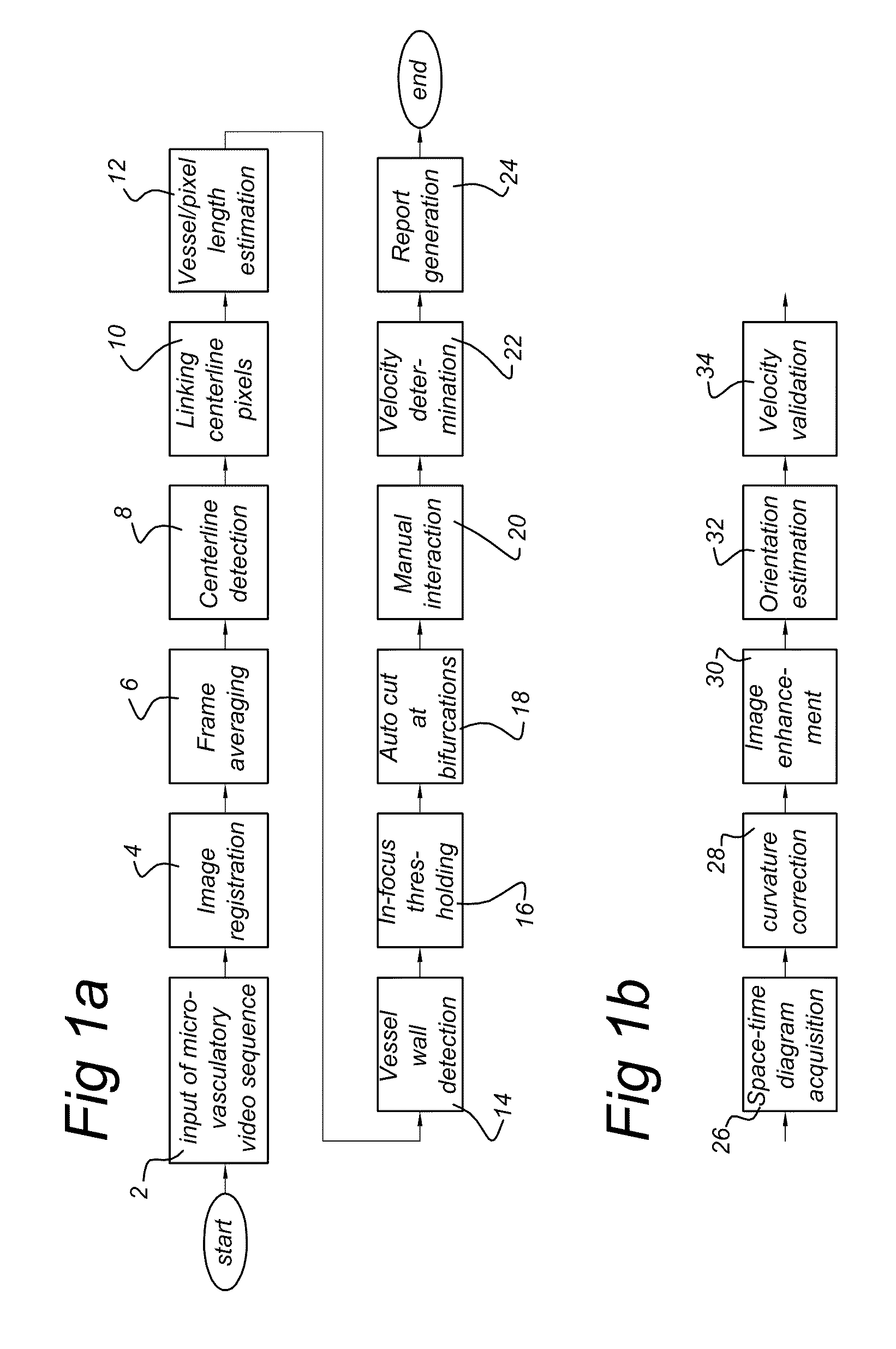
[0051]Vessel segmentation and blood velocity estimation using space-time diagrams requires many image processing steps. FIGS. 1A and 1B show flow charts indicating processing steps according to an embodiment of the invention. These processing steps can be executed by a computer arranged to perform one or more of the processing steps. In a first step 2, a microcirculatory video sequence is received from an imaging system. When making the video sequence, slig...


PUM


Abstract

The invention provides analysis algorithms for quantitative assessment of microvasculatory video sequences that provide vessel thickness, vessel length and blood velocity per vessel segment. It further provides a method of for calculating the functional microvasculatory density and blood velocity as distributed over vessels with different thickness, in the field of view.

Description

TECHNICAL FIELD[0001]The present invention relates to a method of analyzing microvasculatory videos. It more particular relates to the measurement of functional microcirculatory geometry and blood velocity distributions.BACKGROUND[0002]Techniques for studying the human microcirculation in vivo have rapidly evolved in the last few decades. Capillaroscopy is a technique that uses an intravital microscope for imaging the microvascular bed. It has long been the only technique available to study the microcirculation of easy-accessible tissue, such as the skin or the capillary bed under the nail. The microscope-based configuration, however, makes capillaroscopy systems inaccessible to deep-lying tissue. More-recent studies describe the use of Orthogonal Polarization Spectral (OPS) imaging [3, 4, 18, 20, 23, 25, 30] or Side-stream Dark Field (SDF) imaging [13]. These techniques are basically hand-held microscopes with an advanced way of target illumination resulting in a higher contrast th...

Claims


Application Information

Patent Timeline
IPC IPC(8): G06K9/62
CPCA61B5/02007A61B5/0261A61B5/1075G06T2207/30172G06T7/0012G06T7/60G06T2207/30101A61B5/412
Inventor DOBBE, JOHANNES GIJSBERTUS GERARDUS
Owner MVM
Why Eureka
Try Eureka