Turbine engine ring seal

a technology for turbine engines and seals, applied in the field of ring seals, can solve the problems of reducing the interlaminar tensile strength of materials, complicated active cooling systems, and increasing the cost of materials, so as to achieve the effect of reducing the leakage of coolan

Inactive Publication Date: 2010-04-29
SIEMENS ENERGY INC
View PDF21 Cites 56 Cited by
  • Summary
  • Abstract
  • Description
  • Claims
  • Application Information

AI Technical Summary

Benefits of technology

[0018]Both the first ring seal segment and the second ring seal segment can include opposite circumferential ends. One of the circumferential ends of the first ring seal segment can substantially abut one of the circumferential ends of the second ring seal segment so as to define a circumferential interface. The circumferential interface can be substantially sealed to minimize coolant leakage through the circumferential interface. To that end, one or more seals can be attached to the outer surface of the first channel of the first ring seal segment such that they extend circumferentially beyond one of the circumferential ends of the first ring seal segment and into engagement with the outer surface of the first channel of the second ring seal segment. Alternatively or in addition, one or more seals can operatively engage the circumferential ends of the first and second ring seal segments that form the circumferential interface.

Problems solved by technology

Such active cooling systems are usually complicated and costly.
However, CMC materials have their own drawbacks.
Anisotropic shrinkage of the matrix and the fibers can result in delamination defects, particularly in small radius corners and tightly-curved sections, which can further reduce the interlaminar tensile strength of the material.

Method used


Image

  • Turbine engine ring seal
  • Turbine engine ring seal
  • Turbine engine ring seal

Examples


Embodiment Construction

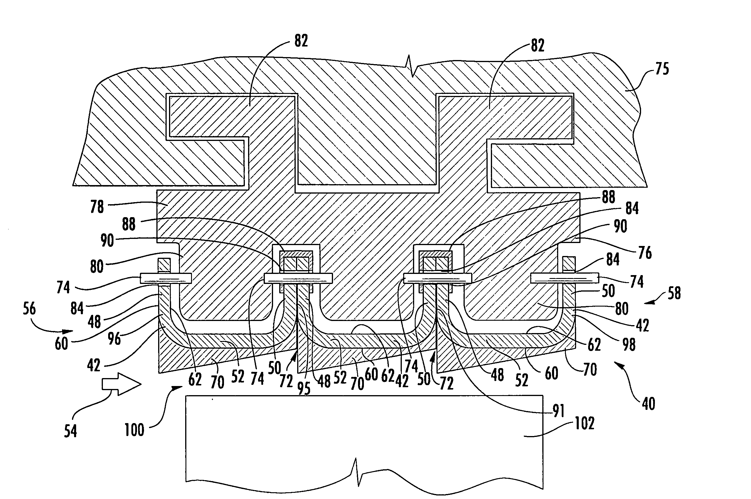
[0027]Embodiments of the invention are directed to a construction for a turbine engine ring seal segment that can better distribute the operational stresses imposed thereon. Aspects of the invention will be explained in connection with one possible ring seal segment, but the detailed description is intended only as exemplary. An embodiment of the invention is shown in FIGS. 2-4, but the present invention is not limited to the illustrated structure or application.

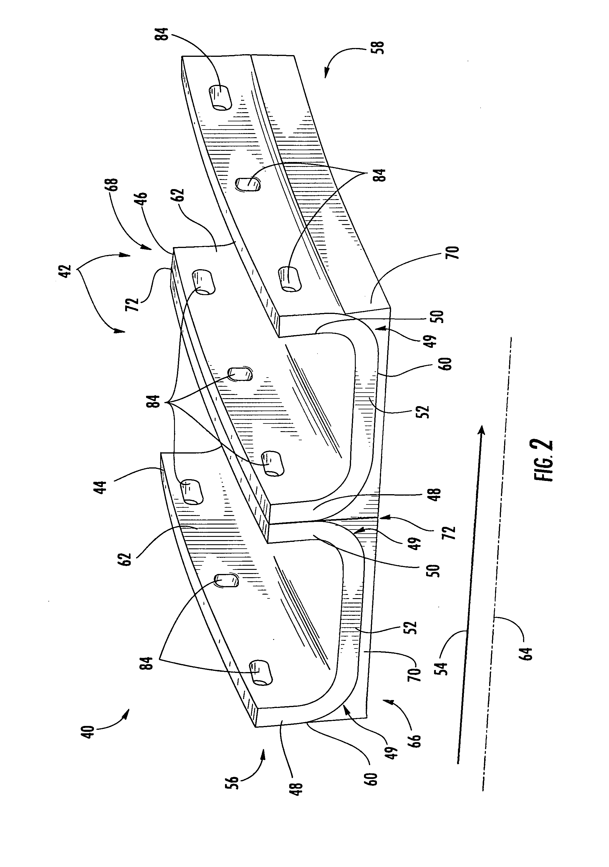
[0028]FIG. 2 shows a ring seal segment 40 according to aspects of the invention.

[0029]The ring seal segment 40 can include a plurality of separate channels 42. In one embodiment, there can be a first channel 44 and a second channel 46. The first and second channels 44, 46 can have a generally U-shaped cross-section. Each of the channels 44, 46 can include a forward span 48 and an aft span 50. The forward span 48 and the aft span 50 of each channel 44, 46 can be connected by an axial extension 52. The terms “forward” and “aft...


PUM


Abstract

Aspects of the invention relate to a ring seal for a turbine engine. The ring seal can be made up of a plurality of circumferentially abutted ring seal segments. Each ring seal segment can comprise a plurality of individual channels. The channels can be generally U-shaped in cross-section with a forward span, and aft span and an extension connecting therebetween. The channels can be positioned such that the aft span of one channel can substantially abut the forward span of another channel. The plurality of separate channels can be detachably coupled to each other by, for example, a plurality of pins. The ring seal segment according to aspects of the invention can facilitate numerous advantageous characteristics including greater material selection, selective cooling, improved serviceability, and reduced blade tip leakage. Moreover, the configuration is well suited to handle the operational loads of the turbine.

Description

FIELD OF THE INVENTION[0001]Aspects of the invention relate in general to turbine engines and, more particularly, to ring seals in the turbine section of a turbine engine.BACKGROUND OF THE INVENTION[0002]FIG. 1 shows an example of one known turbine engine 10 having a compressor section 12, a combustor section 14 and a turbine section 16. In the turbine section 16 of a turbine engine, there are alternating rows of stationary airfoils 18 (commonly referred to as vanes) and rotating airfoils 20 (commonly referred to as blades). Each row of blades 20 is formed by a plurality of airfoils 20 attached to a disc 22 provided on a rotor 24. The blades 20 can extend radially outward from the discs 22 and terminate in a region known as the blade tip 26. Each row of vanes 18 is formed by attaching a plurality of vanes 18 to a vane carrier 28. The vanes 18 can extend radially inward from the inner peripheral surface 30 of the vane carrier 28. The vane carrier 28 is attached to an outer casing 32,...

Claims


Application Information

Patent Timeline
Patent Type & Authority Applications(United States)
IPC IPC(8): F02C7/28
CPCF01D11/12F05D2240/11F05D2230/60
Inventor KELLER, DOUGLAS A.VANCE, STEVEN J.CAMPBELL, CHRISTIAN X.
Owner SIEMENS ENERGY INC
Why Eureka
Try Eureka