Turbine rotor

a turbine rotor and rotor body technology, applied in the direction of liquid fuel engines, vessel construction, marine propulsion, etc., can solve the problems of reducing the performance of the turbine, reducing the efficiency of the turbine, and non-uniform thermal deformation, so as to prevent wear and damage, and simple structure

Inactive Publication Date: 2006-02-07
MITSUBISHI HITACHIPOWER SYST LTD
View PDF11 Cites 10 Cited by
  • Summary
  • Abstract
  • Description
  • Claims
  • Application Information

AI Technical Summary

Benefits of technology

[0021]A first object of the present invention is to provide a turbine rotor which can fix the heat resisti...

Problems solved by technology

Since the coolant is discharged into the combustion gas flow passage after cooling the blade, the open cooling system causes lowering of the combustion gas temperature, mixing loss of the coolant and the combustion gas and lowering of performance of the turbine to lower efficiency of the turbine.
However, the following problems are encountered in the prior art.
However, when both of the coolant supply paths and coolant recovery paths are admixingly present in the turbine disks and the spacer disks, a temperature of the coolant in the coolant supply paths is about 250 C whereby a temperature absorbing temperature of the blade members is elevated as high as 500 C to cause thermal stress in the component members of the turbine disks and the spacer disks to cause non-uniform thermal deformation.
This causes gaps in the stacking planes between the disk shaped members to be a cause of leakage of the coolant to the stacking planes.
Due to leakage to the stacking planes, predetermined flow rate of coolant to the turbine blades cannot be certainly supplied to cause degradation of reliability and durability of the blade members.
However, in the coolant flow paths in each disk shaped member, the gap is formed between the external diameter of the heat resisting pipe and the internal diameter of the coolant flow path.
This gap may cause extra stress on the heat resisting pipe during operation to lower durability of the heat resisting pipe.
Therefore, a problem is encountered in inserting single long heat resisting pipe.
Furthermore, since the heat resisting pipe transports the coolant for cooling the blade, it is abruptly heated in comparison with each disk member to cause displacement of the heat resisting pipe in axial direction due to thermal elongation.
Increase of wearing can ...

Method used


Image

  • Turbine rotor
  • Turbine rotor
  • Turbine rotor

Examples


first embodiment

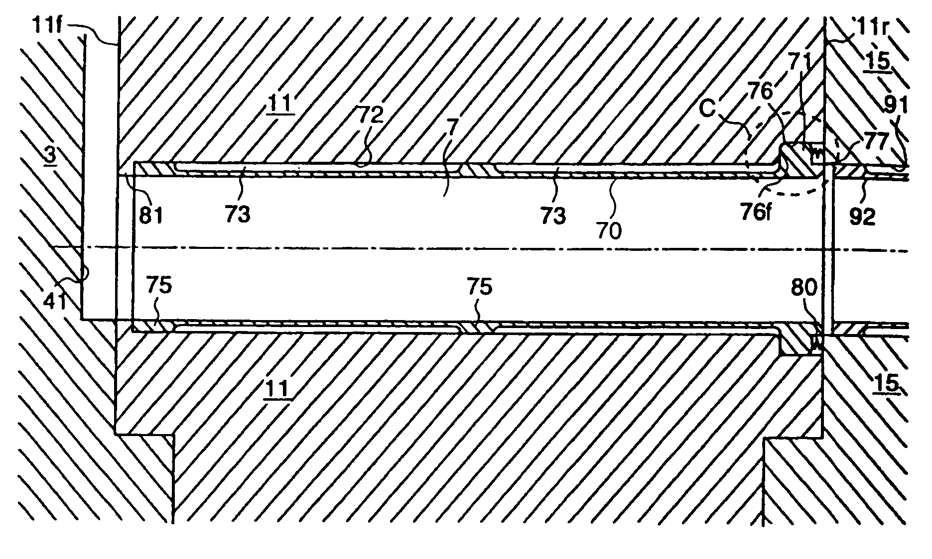
[0051]FIG. 1 is an illustration showing an axial section of a coolant supply path having a heat resisting pipe within a first stage turbine of a turbine rotor according to the present invention. It should be noted that the axial direction in hereinafter commonly refers to an axial direction of the overall turbine rotor and axial direction of a coolant supply path per se, which are in parallel relationship with each other. On the other hand, a radial direction refers to a radial direction of the coolant supply passage per se. On the other hand, in the drawing, left side (upstream side of flow direction of not shown combustion gas) is referred to as front side and right side is referred to as rear side.

[0052]In FIG. 1, the reference numeral 11 denotes a first stage turbine disk, the elements 3 and 15 coupled with stacking planes 11f and 11r on front side and rear side are a distant piece 3 and a spacer disk 15 between the first stage and a second stage. In the first turbine disk, a co...

second embodiment

[0098]the turbine rotor according to the present invention will be discussed with reference to FIG. 11. FIG. 11 is a side elevation of the shown embodiment of the turbine rotor according to the present invention in a condition where the annular seal member and the heat resisting pipe are installed on one of the coolant supply paths 7 of the first stage turbine disk, as viewed from the rear side.

[0099]In FIG. 11, on the outer peripheral surface of the ring-shaped projecting portion 71A of the heat resisting pipe 70, identical shape of projections 74 are provided at two positions located symmetrically with respect to the center axis. On the rear stacking surface of the first stage turbine disk 11A, back facing grooves 78, to which respective projecting portions 74 are engageable on the peripheral positions, to respectively of which two projecting portions 74 match on the outer periphery of the spot facing recess 76A.

[0100]With the embodiment constructed as set forth above, upon operat...


PUM

PropertyMeasurementUnit
Temperatureaaaaaaaaaa

Abstract

A turbine rotor can fix the heat resisting pipes provided in divided form per the disk member with simple structure for preventing wearing and damaging. The turbine rotor includes a coolant flow path formed through a plurality of disc shaped members respectively stacked across stacking planes in axial direction, a heat resisting pipe divided into a plurality of fractions adapted to be inserted into a portion of the coolant flow path defined in each disc shaped member, spot facing recesses each formed at opening portion of coolant flow path at the same side of the disc shaped member coaxially with the coolant flow path and having greater inner diameter than the opening portion, and ring shaped projecting portions formed at respective end portions of the fractions of the heat resisting pipe and engageable with respective spot facing recesses.

Description

[0001]This is a continuation application of U.S. Ser. No. 10 / 352,898, filed Jan. 29, 2003, now U.S. Pat. 6,746,204; which is a divisional application of U.S. Ser. No. 10 / 136,313 filed May 2, 2002, now U.S. Pat. 6,648,600.BACKGROUND OF THE INVENTION[0002]The present invention relates to a turbine rotor formed by stacking disk shaped members in axial direction, and more particularly to a turbine rotor inserted heat resisting pipes by forming therein coolant flow passages in axial direction.DESCRIPTION OF THE RELATED ART[0003]In general, a gas turbine in a thermal power generation plant is constructed with a compressor sucking an air (atmospheric air) and compressing up to a predetermined pressure, a combustor mixing the air compressed by the compressor with a fuel and burning for generating a combustion gas, and a turbine portion generating a driving force by expansion of a high temperature and high pressure combustion gas. Also, a gas turbine power generation facility is constructed ...

Claims


Application Information

Patent Timeline
IPC IPC(8): F01D5/00F01D5/08
CPCF01D5/08F01D5/084Y10T29/49318
Inventor TAKAHASHI, YASUOMARUSHIMA, SHINYAHIGUCHI, SHINICHITAKANO, TSUYOSHI
Owner MITSUBISHI HITACHIPOWER SYST LTD
Why Eureka
Try Eureka