Compact electric grinding machine

a compact, electric technology, applied in the direction of grinding drives, grinding drive, dc motor rotation control, etc., can solve the problems of disadvantageous hermetic motor, unavoidable large motor diameter, and difficulty in gripping one hand

Inactive Publication Date: 2010-04-29
KWH MIRKA
View PDF5 Cites 20 Cited by
  • Summary
  • Abstract
  • Description
  • Claims
  • Application Information

AI Technical Summary

Benefits of technology

[0014]When the control is sensorless, the motor is more compact becau...

Problems solved by technology

The drawback of this solution is that the motor diameter unavoidably becomes large and therefore also difficult to be gripped with one hand.
Further, since the diameter is large, it becomes disadvantageous to make a hermetic motor with cooling only on the outside.
This is very disadvantageous because the air in which the sanding machine is most often used is filled by dust particles that may be both electrically conductive and grinding by nature.
Since electric sanding machines have previously been s...

Method used


Image

  • Compact electric grinding machine
  • Compact electric grinding machine
  • Compact electric grinding machine

Examples


Embodiment Construction

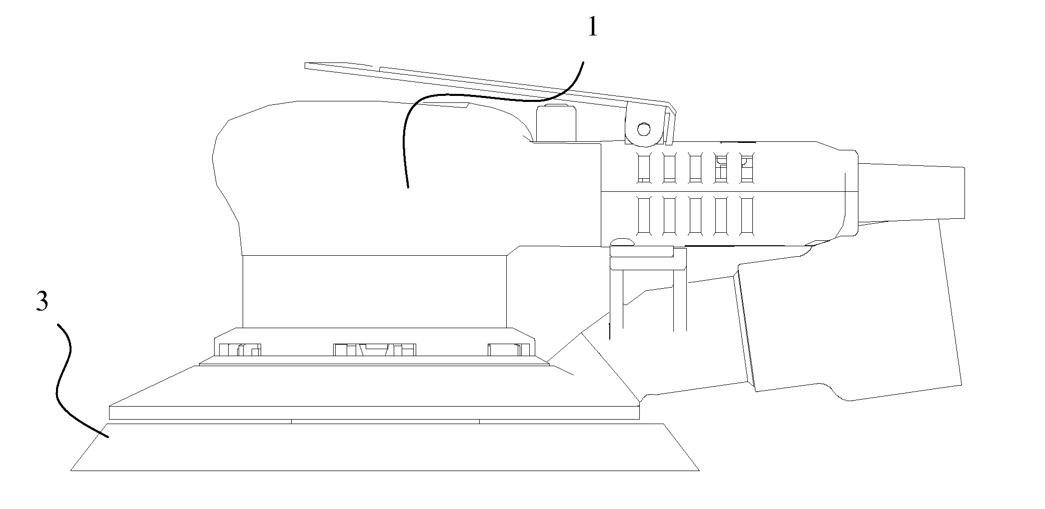
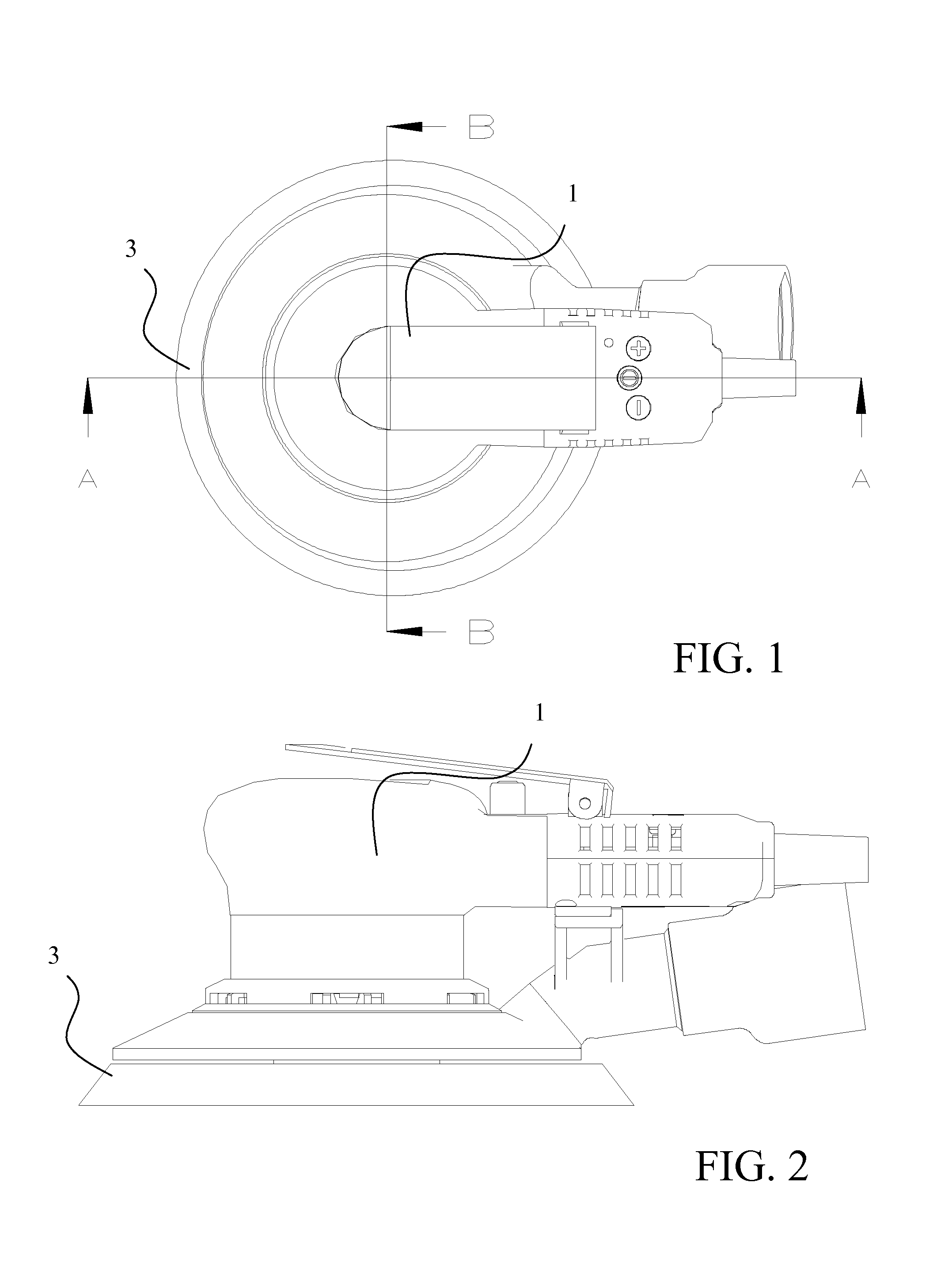
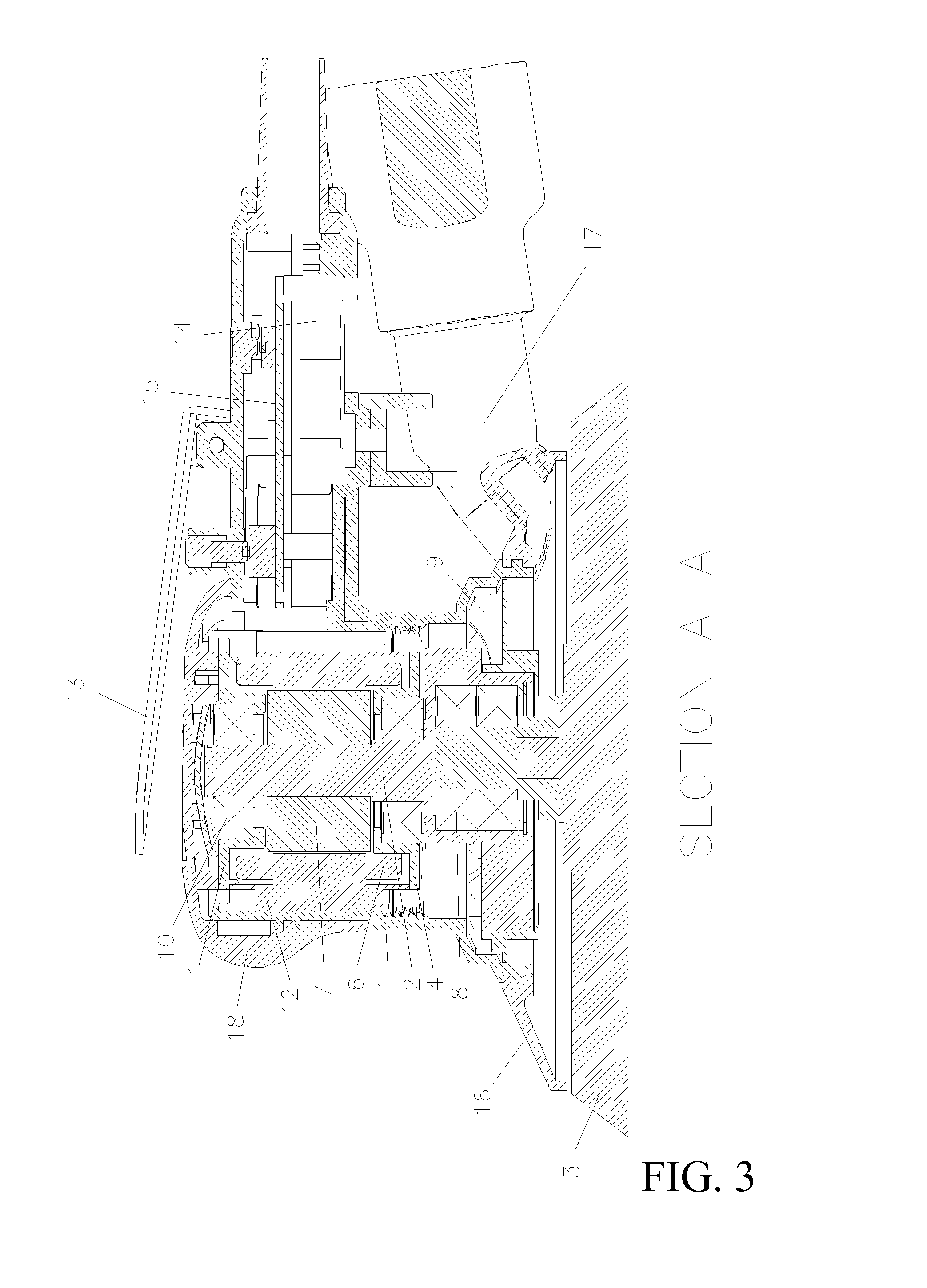
[0025]The sanding machine shown in FIGS. 1 to 4 is formed of a housing 1 enclosing all parts of the motor. The motor is formed of a stator 6, including a casing with cooling fins 12 and a rotor 7. These parts are integrated with the parts keeping a tool shaft 2, a bearing housing at both ends 4, 11 and a bearing 10 in place, in such a way that the rotor 7 is fastened to the tool shaft 2. The casing and cooling fins of the stator 6 are shaped in such a way that an air slot is generated which is limited by the casing, the housing of the sanding machine and the cooling fins. The grinding disc 3 is fastened freely rotationally to the tool shaft 2 via an eccentric bearing 8. The blower 9, which is fastened to the tool shaft 2 preferably at the same height as the balance weights, sucks in air through the hole 14. The air cools the control unit 15 and then the motor via the cooling fins 12. The air is blown out through the hole 5. The shroud 16 collects the grinding dust that is sucked out...


PUM

PropertyMeasurementUnit
Electrical inductanceaaaaaaaaaa
Speedaaaaaaaaaa
Currentaaaaaaaaaa

Abstract

The present invention particularly relates to a hand-held sanding machine with an outer housing (1), a tool shaft (2) and a brushless electric drive motor. In the present invention, the rotor of the drive motor is fastened to the tool shaft (2) of the sanding machine, and the stator (6) is positioned in the outer housing (1). The present invention also relates to a control method for an electric sanding machine.

Description

TECHNICAL FIELD[0001]The present invention relates to an compact electric hand-held sanding machine with an outer housing and a tool shaft.PRIOR ART[0002]Electric sanding machines of the same type are previously known from, for example, U.S. Pat. No. 0,245,182. Here, the intention has been to make a relatively compact and low sanding machine by using a brushless motor and making the proportion between the motor diameter and the motor height great. The drawback of this solution is that the motor diameter unavoidably becomes large and therefore also difficult to be gripped with one hand. Further, since the diameter is large, it becomes disadvantageous to make a hermetic motor with cooling only on the outside. This is very disadvantageous because the air in which the sanding machine is most often used is filled by dust particles that may be both electrically conductive and grinding by nature.[0003]Since electric sanding machines have previously been so large and heavy, it has been nece...

Claims


Application Information

Patent Timeline
IPC IPC(8): B24B23/02B24B1/00
CPCB24B23/00B24B23/02B24B47/12B23Q11/127B24B23/04H02P29/00H02P6/00H02M1/4208H02M1/4225Y02P70/10H02M1/4291H02P7/05H02P27/00
Inventor NORDSTROM, CAJ
Owner KWH MIRKA
Why Eureka
Try Eureka