
Method of manufacturing solid electrolytic capacitor

a manufacturing method and electrolytic capacitor technology, applied in the manufacture of electrolytic capacitors, capacitor details, electrolytic capacitors, etc., can solve the problems of increased and achieve the suppression of leak current and short circuit occurrence, high voltage proof property, and high reliability

Active Publication Date: 2010-05-06
PANASONIC INTELLECTUAL PROPERTY MANAGEMENT CO LTD
View PDF8 Cites 15 Cited by
  • Summary
  • Abstract
  • Description
  • Claims
  • Application Information

AI Technical Summary

Benefits of technology

[0015]According to the present invention, a solid electrolytic capacitor using a conductive polymer as a solid electrolyte, in which increase of leak current and occurrence of a short circuit are suppressed, and which has a high voltage proof property and high reliability can be provided.

Problems solved by technology

However, when the chemical conversion voltage is increased, there occur problems such as increase of leak current due to degradation in leak current property, occurrence of a short circuit, and the like.

Method used


Image

  • Method of manufacturing solid electrolytic capacitor
  • Method of manufacturing solid electrolytic capacitor
  • Method of manufacturing solid electrolytic capacitor

Examples


example 1

[0033]Firstly, etching treatment was performed on surfaces of anode body 2 and cathode body 3 made of aluminum foil. Thereafter, a dielectric coating film was formed on the surface of anode body 2 by immersing anode body 2 subjected to etching treatment in a chemical conversion solution and applying a voltage of 150 V.

[0034]Anode lead tab 7A and cathode lead tab 7B were connected to anode body 2 and cathode body 3, respectively. Then, anode body 2 and cathode body 3 were wound together with separator 12, and the outermost periphery was secured with winding stop tape 5 to fabricate capacitor element 6.

[0035]Subsequently, capacitor element 6 was subjected to chemical conversion treatment of a cut section. Chemical conversion treatment of a cut section was performed by immersing capacitor element 6 in a chemical conversion solution and applying voltage.

[0036]Then, a polymerization liquid for a conductive polymer as a solid electrolyte was prepared. As a monomer, 3,4-ethylenedioxythioph...

example 2

[0040]A solid electrolytic capacitor was fabricated as in Example 1 except for setting the weight percentages of the monomer, the oxidant, and the silane compound to 25 wt %, 72 wt %, and 3 wt %, respectively.

example 3

[0041]A solid electrolytic capacitor was fabricated as in Example 1 except for setting the weight percentages of the monomer, the oxidant, and the silane compound to 25 wt %, 70 wt %, and 5 wt %, respectively.


PUM

PropertyMeasurementUnit
temperatureaaaaaaaaaa

Abstract

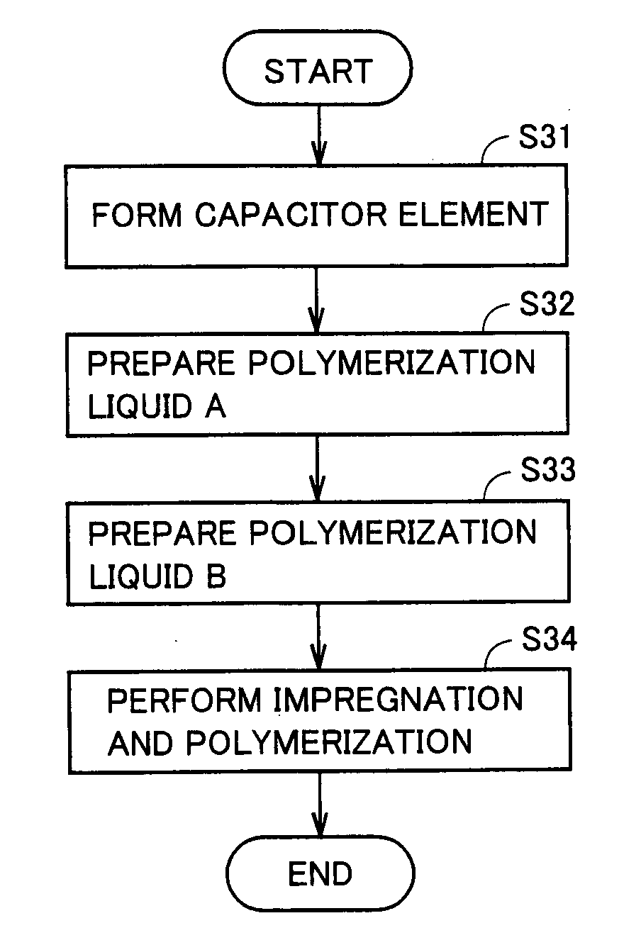
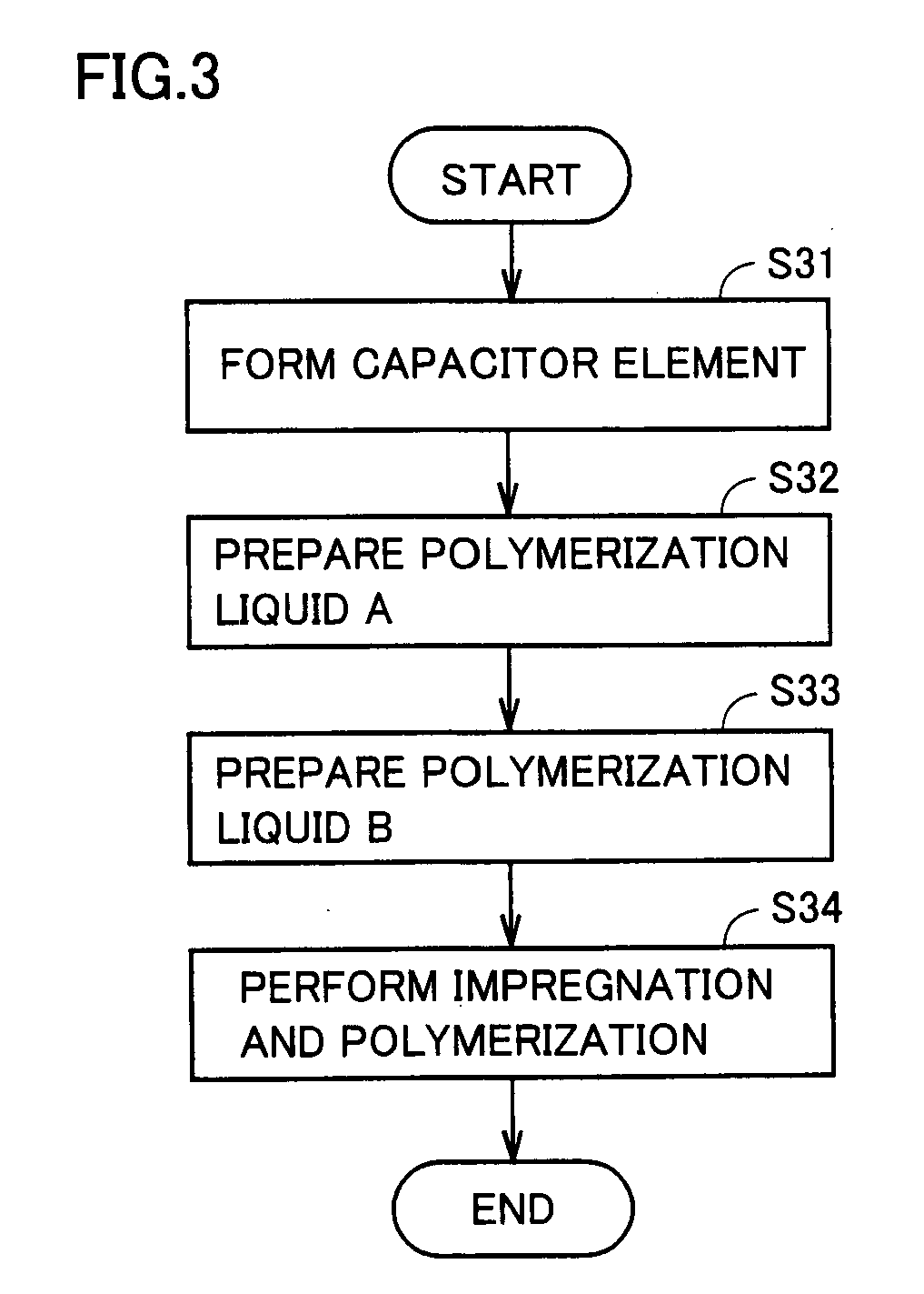
Provided is a method of manufacturing a solid electrolytic capacitor including a capacitor element, the capacitor element having an anode body with a dielectric coating film formed on a surface thereof and a solid electrolyte made of a conductive polymer. The method includes the steps of: forming the capacitor element having the anode body with the dielectric coating film formed on the surface thereof; preparing a polymerization liquid A containing one of a monomer as a precursor of the conductive polymer and an oxidant, and a silane compound; preparing a polymerization liquid B by adding the other of the monomer and the oxidant that is not contained in polymerization liquid A, to polymerization liquid A; and performing polymerization after impregnating the capacitor element with polymerization liquid B.

Description

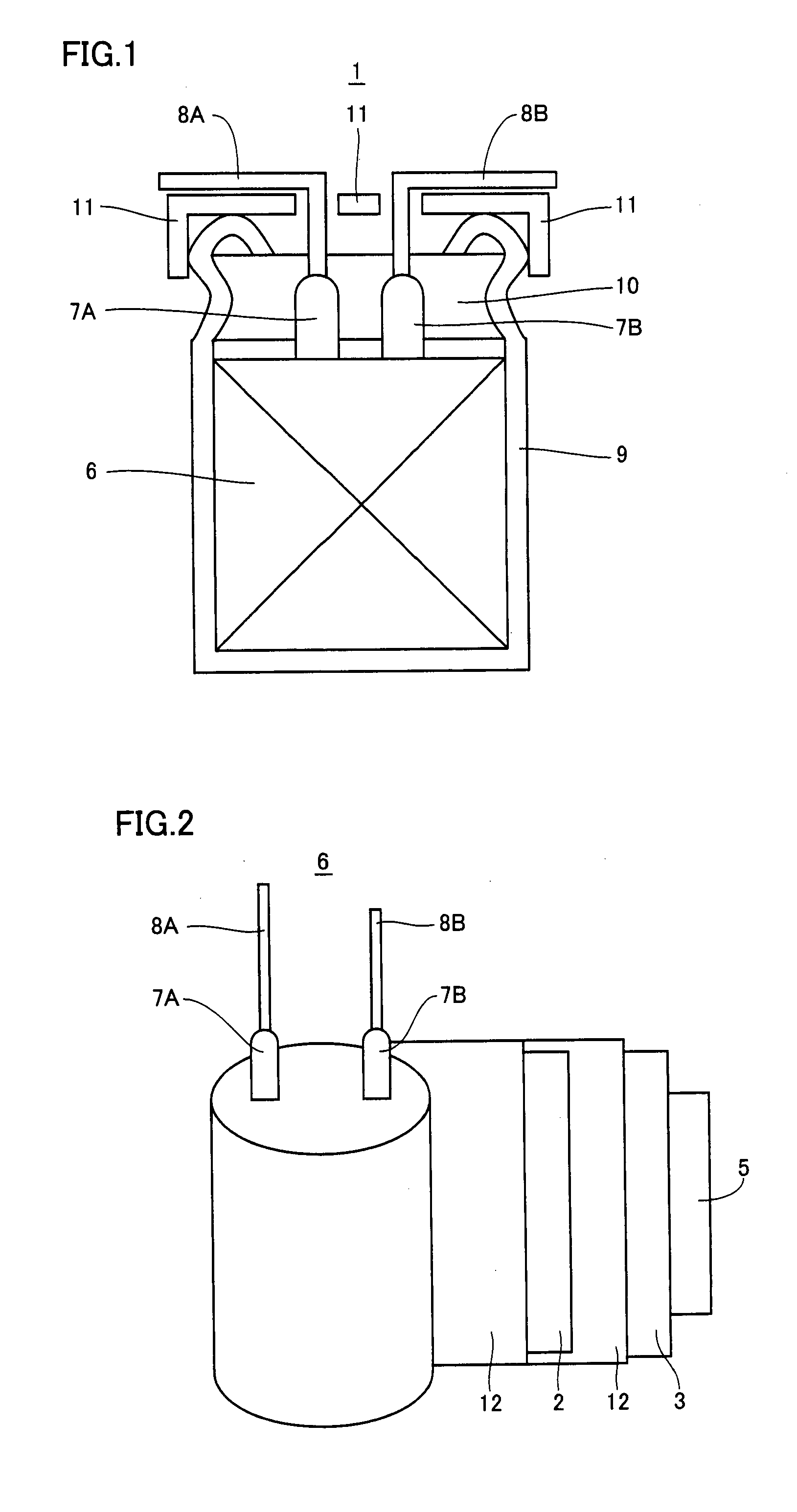
BACKGROUND OF THE INVENTION[0001]1. Field of the Invention[0002]The present invention relates to a method of manufacturing a solid electrolytic capacitor.[0003]2. Description of the Background Art[0004]As a typical solid electrolytic capacitor, the one shown in FIGS. 1 and 2 is known (Japanese Patent Laying-Open No. 10-144574).[0005]As shown in a cross sectional view of FIG. 1, a solid electrolytic capacitor 1 has a capacitor element 6 having leads 8A and 8B, a bottomed case 9 accommodating capacitor element 6, and a sealing member 10 sealing capacitor element 6. The vicinity of an opening end of bottomed case 9 is subjected to pressing in a lateral direction and curling.[0006]As shown in a perspective view of FIG. 2, capacitor element 6 is formed by winding an anode body 2 having a dielectric coating film formed on a surface thereof and a cathode body 3 together, with a separator 12 being interposed therebetween, and thereafter securing the wound object with a winding stop tape 5, ...

Claims


Application Information

Patent Timeline
Patent Type & Authority Applications(United States)
IPC IPC(8): H01G9/15H01G9/025
CPCH01G9/0036H01G9/028H01G9/15H01G11/56Y02E60/13Y10T29/417Y10T29/49117H01G9/012
Inventor FURUKAWA, TAKESHIINUTSUKA, YUICHIRO
Owner PANASONIC INTELLECTUAL PROPERTY MANAGEMENT CO LTD
Learn More