

Method of manufacturing solid electrolytic capacitor
a manufacturing method and technology applied in the manufacture of electrolytic capacitors, fixed capacitors, cell components, etc., can solve the problems of increasing the leak current of solid electrolytic capacitors, and achieves the effects of reducing the short circuit occurrence ratio, reducing the leak current, and high reliability
- Summary
- Abstract
- Description
- Claims
- Application Information
AI Technical Summary
Benefits of technology
Problems solved by technology
Method used
Image

Examples
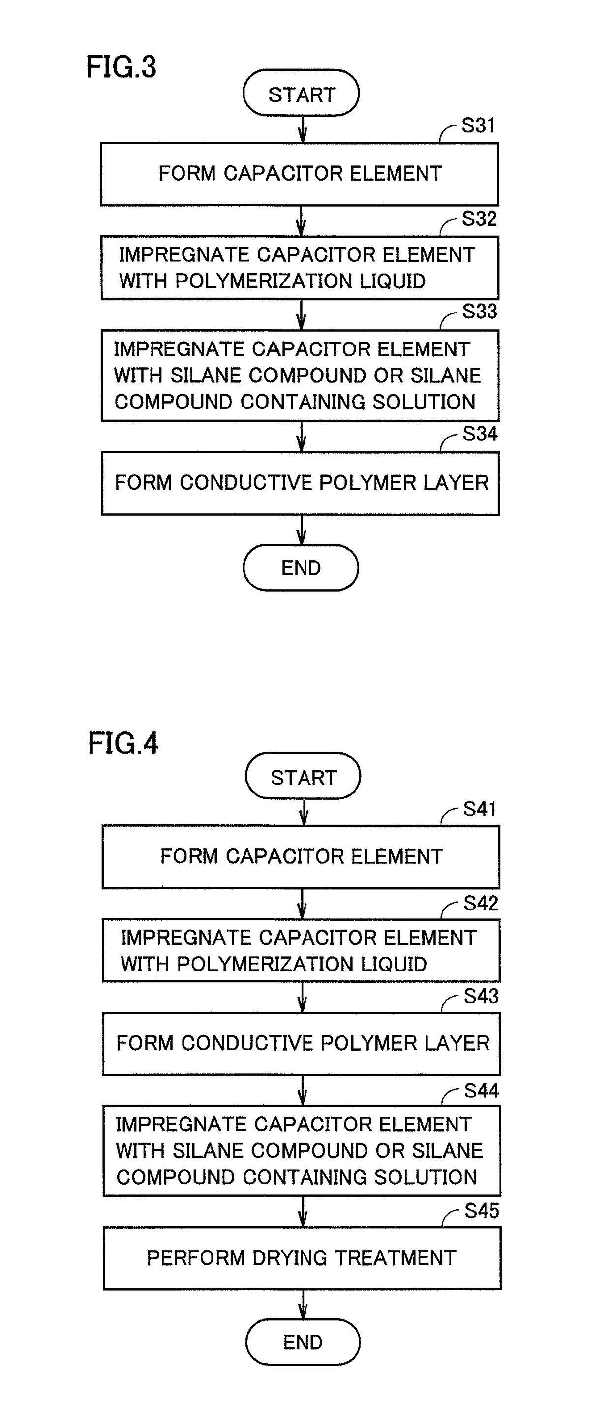
first embodiment
EXAMPLES OF THE FIRST EMBODIMENT
Example 1
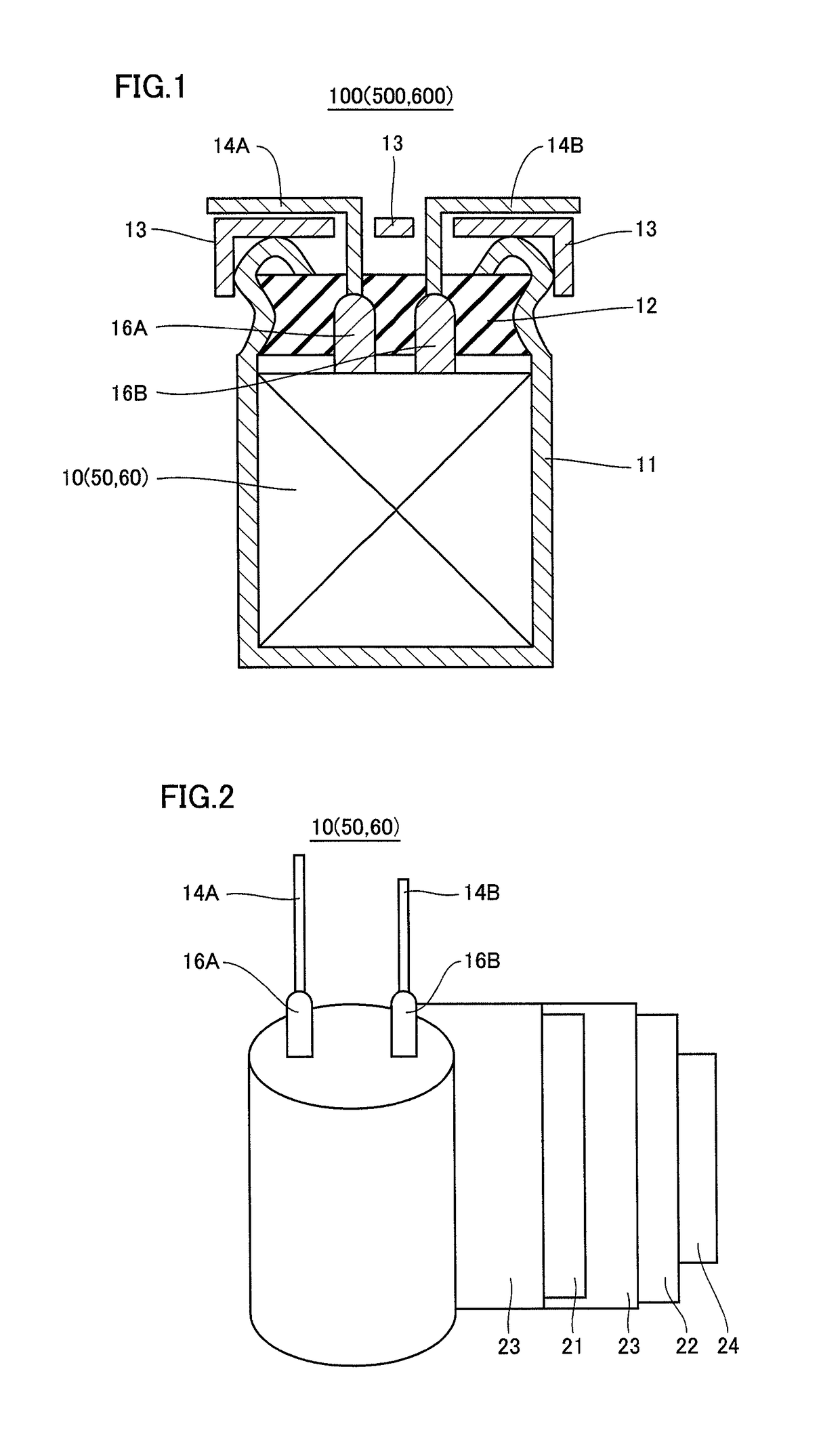
[0062]Firstly, etching treatment was performed on surfaces of anode body 21 and cathode body 22 made of aluminum foil. Thereafter, a dielectric coating film was formed by immersing anode body 21 subjected to etching treatment in a chemical conversion solution and applying a voltage of 150 V.
[0063]Lead tab 16A and lead tab 16B were connected to anode body 21 and cathode body 22, respectively. Then, anode body 21 and cathode body 22 were wound together with separator 23, and the outermost periphery was secured with winding stop tape 24 to fabricate capacitor element 50.
[0064]Subsequently, capacitor element 50 was subjected to chemical conversion treatment of a cut section. Chemical conversion treatment of a cut section was performed by immersing capacitor element 50 in a chemical conversion solution and applying voltage.
[0065]Next, a polymerization liquid was prepared. The polymerization liquid was prepared by mixing 3,4-ethylenedioxythiophene ...
example 2
[0069]A solid electrolytic capacitor was fabricated as in Example 1 except for setting the concentration of the silane compound in the silane compound containing solution to 20 wt %.
example 3
[0070]A solid electrolytic capacitor was fabricated as in Example 1 except for setting the concentration of the silane compound in the silane compound containing solution to 50 wt %.
PUM
| Property | Measurement | Unit |
|---|---|---|
| temperature | aaaaa | aaaaa |
| temperature | aaaaa | aaaaa |
| voltage | aaaaa | aaaaa |
Abstract
Description
Claims
Application Information