Dual-circuit chiller with two-pass heat exchanger in a series counterflow arrangement

Active Publication Date: 2010-05-06
CARRIER CORP
View PDF23 Cites 13 Cited by
  • Summary
  • Abstract
  • Description
  • Claims
  • Application Information

AI Technical Summary

Benefits of technology

[0008]Briefly, in accordance with one aspect of the invention, each circuit has unique tubesheets that separate the refrigeration circuit from the cooling medium. Between each circuit is an intermediate

Problems solved by technology

One problem that arises is that of servicing the tubes such as may be required if a tube fails in operation.
It is not possible to completely remove a tube since there is no access to cut the tube at the center tubesheet location, which is inside the refrigerant boundary.
If a tube is cut internally, or if a tube fails in operation, a leak path is created between the circuits that does not allow for operation of either circuit, thus adversely impacting both reliability and serviceability.
Another problem with a dual circuit system is that of control.
Since the water tubes spa

Method used


Image

  • Dual-circuit chiller with two-pass heat exchanger in a series counterflow arrangement
  • Dual-circuit chiller with two-pass heat exchanger in a series counterflow arrangement
  • Dual-circuit chiller with two-pass heat exchanger in a series counterflow arrangement

Examples


Example

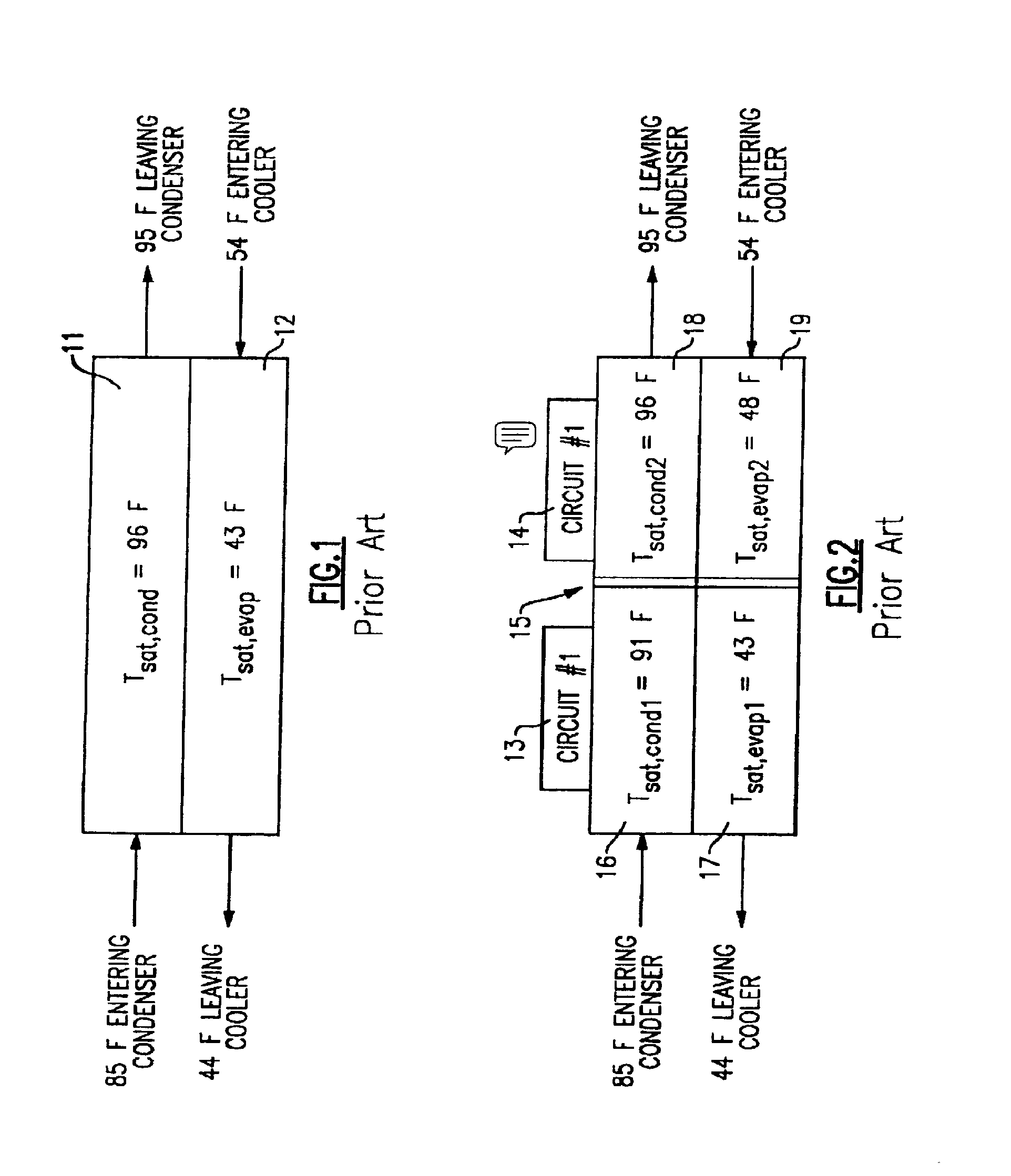
[0024]FIG. 1 shows a condenser 11 and a cooler or evaporator 12 of a single circuit chiller that is typical of the prior art. As shown, the condenser water and evaporator water flows in a counterflow relationship, and the resulting temperatures entering and leaving the condenser and evaporator are as shown.

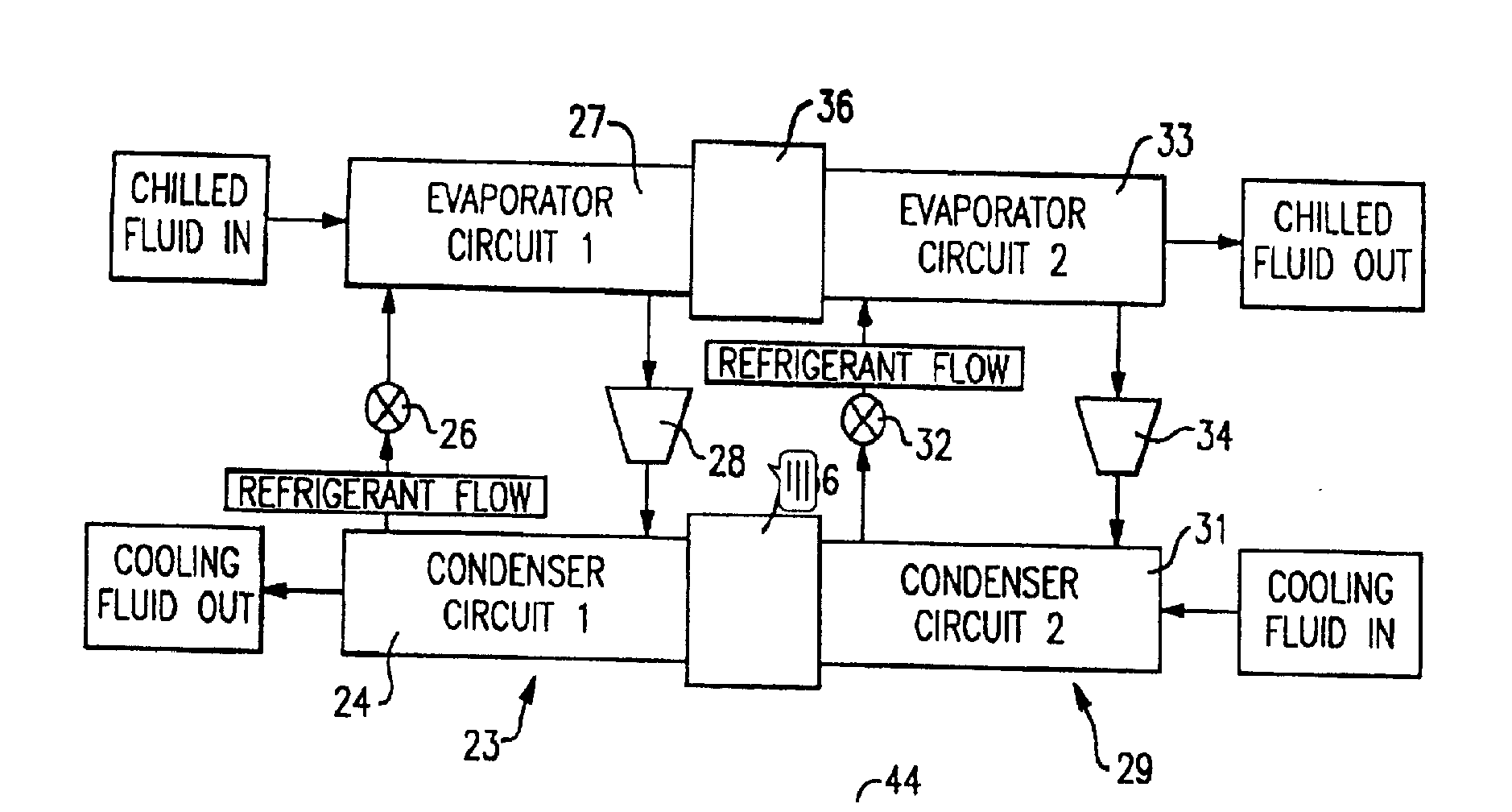
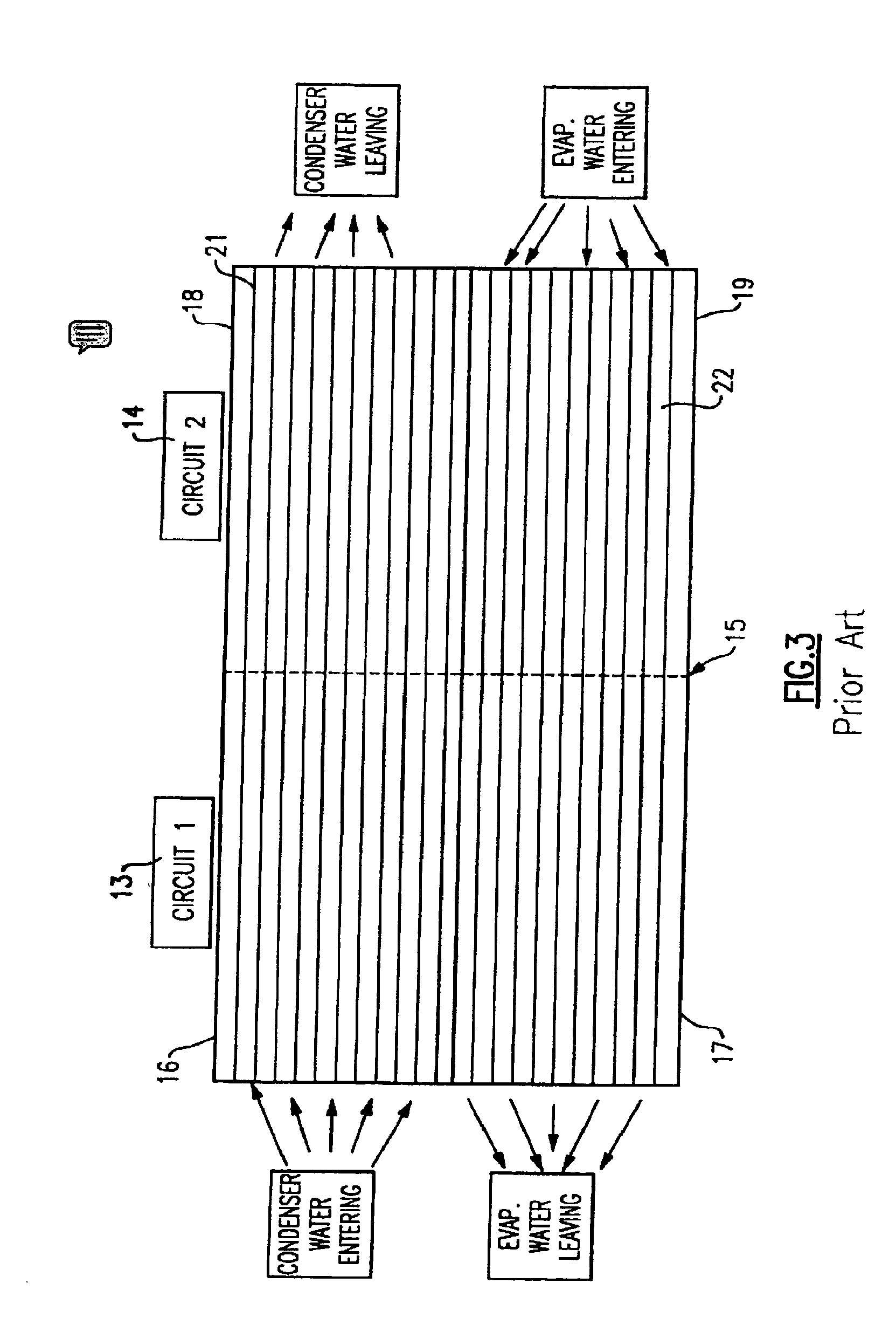
[0025]In order to obtain increased COPs, a dual-circuit is connected in series counterflow arrangement as shown in FIG. 2. Here, two independent vapor compression refrigeration circuits, 13 and 14, are connected by an intermediate tubesheet 15 as shown. The first circuit 13 has a condenser 16 and an evaporator 17, and the second circuit 14 has its own condenser 18 and evaporator 19. However, the condenser water circuits of the condenser 16 and 18 are common to both circuits and are arranged in series. Also, the chilled water circuits of the evaporators 17 and 19 are common to both circuits and are arranged in series. This can be best seen by reference to FIG. 3.

[0026]It will be se...


PUM


Abstract

A dual refrigeration circuit, watercooled chiller has its respective evaporators and condensers interconnected by waterboxes, with each waterbox having an inlet flow and outlet flow connection, and with three passages interconnected with the respective evaporators/condensers of the first and second circuit, and with each of the condensers/evaporators having return bends at their ends to provide a two-pass flow arrangement. The flow in the condenser waterbox passes into a first passage and then in one direction to the condenser of one circuit while the flow into the evaporator waterbox passes into a first passage and then in the opposite direction to one of the circuit evaporators. In this manner, a series counterflow arrangement with two water passes is achieved.

Description

BACKGROUND OF THE INVENTION[0001]This invention relates generally to water cooled chillers and, more specifically, to the interconnection of two vapor compression refrigeration systems in a series-counterflow arrangement.[0002]Water cooled chillers in a series-counterflow arrangement consist of two independent vapor compression refrigeration systems with chilled water and condenser water circuits that are common to both circuits and are arranged in series. This arrangement allows for an increased coefficient of performance (COP) over a single refrigeration circuit design because the separate circuits with series counterflow have a lower average pressure differential between the evaporator and condenser, thus requiring less energy to compress refrigerant from the evaporator to the condenser.[0003]In such a system, water in each of the evaporators and the condensers flows through a plurality of tubes that span both refrigeration circuits, with the refrigeration circuits being separate...

Claims


Application Information

Patent Timeline
IPC IPC(8): F25B1/10
CPCF25B1/00F25B39/00F25B2339/047F25B2400/06F25B2700/21161F28D7/0066F28D7/0091F28F9/02F28F2280/02
Inventor MACBAIN, SCOTT M.STARK, MICHAEL A.
Owner CARRIER CORP
Why Eureka
Try Eureka