Method for increasing torsional fatigue strength in crankshafts

a crankshaft and torsional fatigue technology, which is applied in the direction of crankshafts, engine components, mechanical equipment, etc., can solve the problems of increased engine output power, crankshaft rotation, and severe stresses on the crankshaft, and achieve the effect of increasing the torsional fatigue strength of the cast iron cranksha

Inactive Publication Date: 2010-05-06
CUMMINS INTPROP INC
View PDF3 Cites 26 Cited by
  • Summary
  • Abstract
  • Description
  • Claims
  • Application Information

AI Technical Summary

Benefits of technology

[0006]In one embodiment of the present disclosure, the torsional fatigue strength of a cast iron crankshaft is increased through roller burnishing the interior of the oil

Problems solved by technology

Modern engines, such as diesel engines for vehicles, produce significant power through fuel combustion, which causes reciprocal motion of pistons, which in turn cause rotation of a crankshaft.
The stresses on the crankshaft are severe, and increase with engine output power.
It is known that one of the areas of the crankshaft most susceptible to failure as a result of torsional stress is the area of the crank

Method used


Image

  • Method for increasing torsional fatigue strength in crankshafts
  • Method for increasing torsional fatigue strength in crankshafts
  • Method for increasing torsional fatigue strength in crankshafts

Examples


Embodiment Construction

[0011]For the purposes of promoting an understanding of the principles of the invention, reference will now be made to the embodiments illustrated in the drawings, which are described below. It will nevertheless be understood that no limitation of the scope of the invention is thereby intended. The invention includes any alterations and further modifications in the illustrated device and described method and further applications of the principles of the invention, which would normally occur to one skilled in the art to which the invention relates. Moreover, the embodiments were selected for description to enable one of ordinary skill in the art to practice the invention.

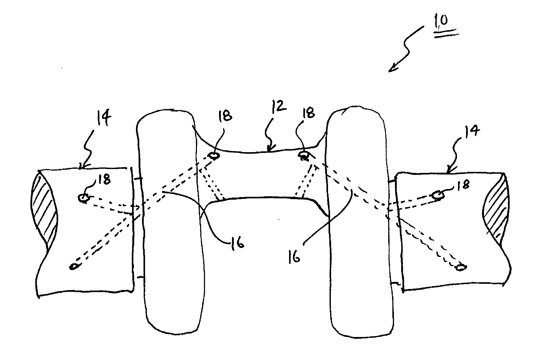
[0012]Referring now to FIG. 1, a portion of a crankshaft 10 is depicted as including a crank pin bearing 12 and a pair of main bearings 14. As is well understood by those skilled in the art, crank pin bearing 12 is coupled to a connecting rod (not shown) at the opposite end of a piston (not shown). Main bearings 14 a...


PUM

PropertyMeasurementUnit
Lengthaaaaaaaaaa
Angleaaaaaaaaaa
Diameteraaaaaaaaaa

Abstract

A method for processing a cast iron crankshaft to improve the torsional fatigue strength of the crankshaft includes forming oil holes into a portion of the crankshaft, treating the portion of the crankshaft to harden an annular area of the portion, and roller burnishing a length of the interior of the oil holes to an increased diameter. The roller burnished length of the oil holes extending from a surface of the crankshaft to at least beyond the hardened annular area.

Description

FIELD OF THE INVENTION[0001]The present invention generally relates to processes for increasing fatigue strength in materials for use on engines, and more particularly to processes for increasing the torsional fatigue strength of cast iron materials to permit use of such materials in the production of engine crankshafts.BACKGROUND OF THE INVENTION[0002]Modern engines, such as diesel engines for vehicles, produce significant power through fuel combustion, which causes reciprocal motion of pistons, which in turn cause rotation of a crankshaft. The rotating crankshaft is coupled to various systems on the vehicle, including the transmission, to cause rotation of wheels and motion of the vehicle.[0003]The stresses on the crankshaft are severe, and increase with engine output power. One of the stresses imparted to the crankshaft is torsional stress, which is a type of shear stress resulting from the forces urging the crankshaft to twist substantially along its longitudinal axis during ope...

Claims


Application Information

Patent Timeline
IPC IPC(8): F16C3/14B23P17/00F16C3/06
CPCB23P9/02B23P15/00B23P2700/07F16C3/14Y10T74/2185Y10T29/49286F16C3/08F16C2360/22
Inventor ALDERTON, ROSS W.PURCELL, JOHN J.SAXBY, STEPEHN J.
Owner CUMMINS INTPROP INC
Why Eureka
Try Eureka