
System and method for fluid flow control

a fluid flow and control system technology, applied in the direction of liquid/fluent solid measurement, water supply installation, application, etc., can solve the problems of inaccuracy in flow measurement, no automatic control of pressure or flow, and additional problems in relation

Inactive Publication Date: 2010-05-06
SIPCO
View PDF0 Cites 5 Cited by
  • Summary
  • Abstract
  • Description
  • Claims
  • Application Information

AI Technical Summary

Benefits of technology

[0023]Preferably said means of suppressing pressure pulses upstream of said means of measuring the actual liquid flow rate is in the form of a damp

Problems solved by technology

Typically, this scheme is manually set and has no automatic control of the pressure or flow.
Measuring the flow rate of fluid from pumps commonly used in agricultural implements has presented a problem, being that most of the pumps used are diaphragm pumps which send pressure pulses along the hoses which typically cause inaccuracies in the flow measurement.
Exacerbating this problem is the overpressure valves and / or switches built into the pumps which may often cut in and out causing additional problems in relation to pressure change.

Method used


Image

  • System and method for fluid flow control
  • System and method for fluid flow control
  • System and method for fluid flow control

Examples


Embodiment Construction

[0044]The following detailed description of the invention refers to the accompanying drawings. Although the description includes exemplary embodiments, other embodiments are possible, and changes may be made to the embodiments described without departing from the spirit and scope of the invention. Wherever possible, the same reference numbers will be used throughout the drawings and the following description to refer to the same and like parts.

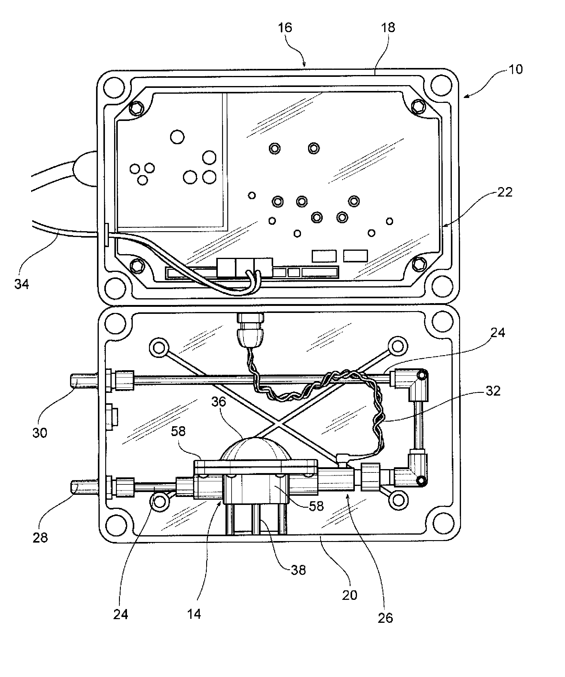
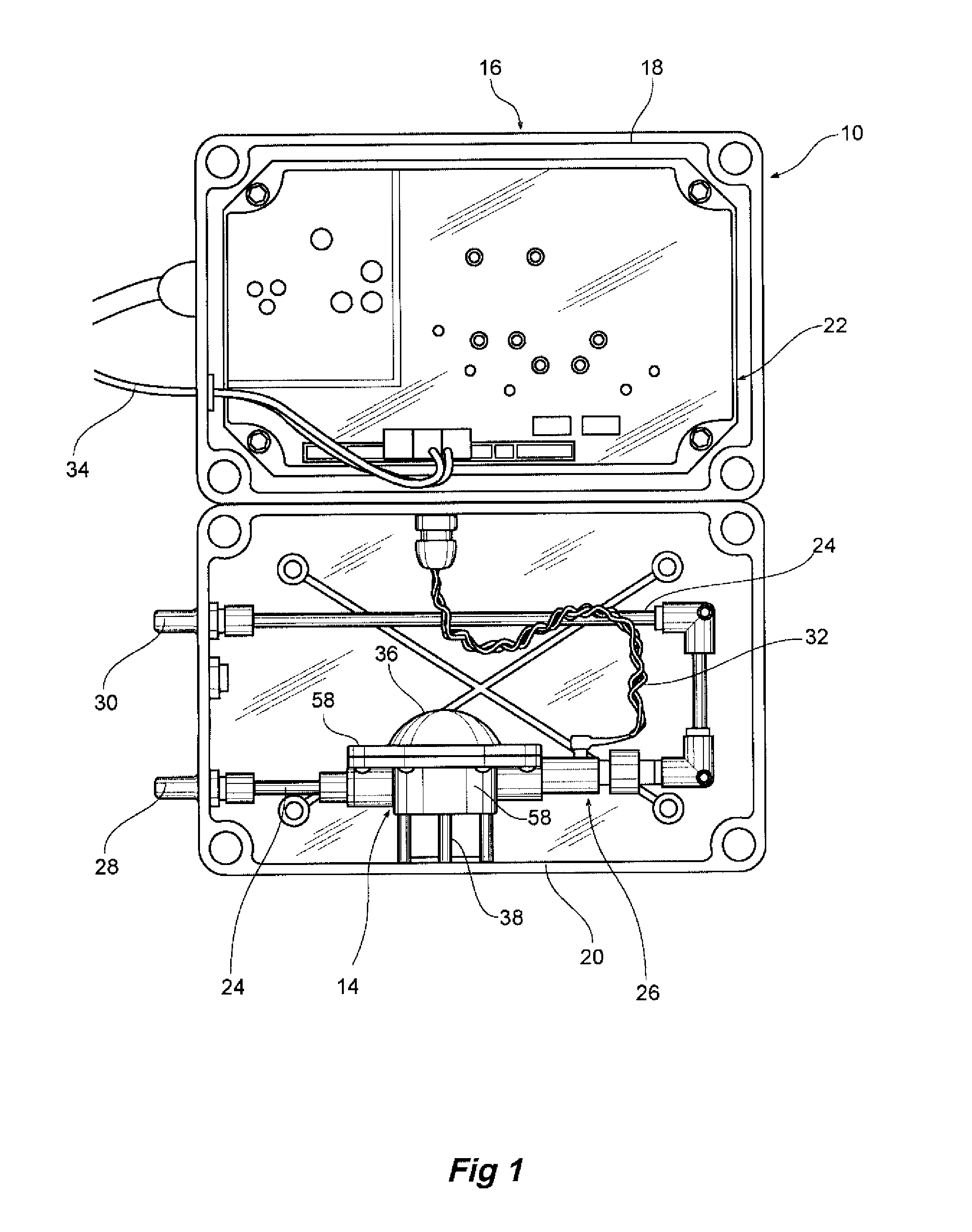
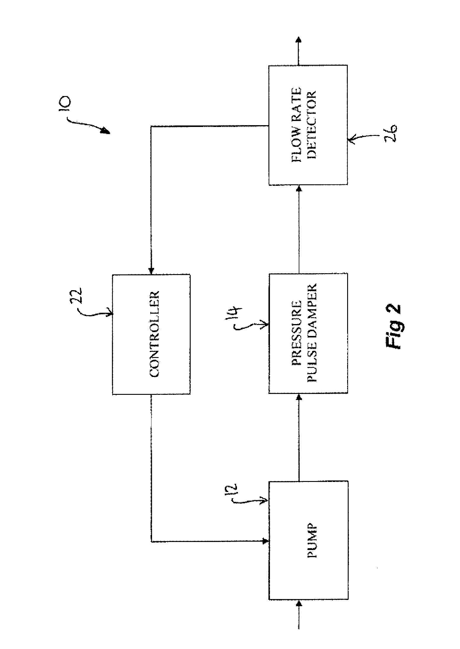
[0045]The present invention relates to an electronic control system 10 for particular use on a hay baler (not shown) of the type having a liquid preservative tank (not shown), and a pump 12 for pumping preservative from the tank to a spray nozzle (not shown), which in turn is used to apply the preservative to fodder (not shown). However, the present invention is not intended to be limited to such use, and could equally well be used in any mobile machine which requires the flow rate of liquid to be controlled in accordance with various detected...


PUM


Abstract

The present invention relates to a system and method for fluid flow control, for particular user in a hay baler. The system involves calculating or inputting a preferred flow rate (the Set Point), measuring the “actual” flow rate of liquid through the system, and controlling the speed of a pump used to move the liquid through the system to ensure that the flow rate is maintained as close as possible to the Set Point flow rate at all times during operation. The flow rate Set Point can be calculated using one or more user or sensor inputs, including the dose rate, the mass flow rate of fodder, the moisture content, etc.

Description

[0001]The present invention relates to a system and method for fluid flow control and, in particular, to a system for accurately controlling the flow rate of liquid from a pump, by firstly smoothing out pressure pulses, measuring the flow rate, and adjusting power to the pump accordingly. The invention is intended for particular use in controlling the flow rate of preservative in a hay baler.BACKGROUND OF THE INVENTION[0002]Many agricultural implements require the use of a pump to supply liquids such as inoculants and preservatives directly to agricultural products using spray nozzles and the like. These pumps are also used to supply a dose of chemicals, such as herbicides and pesticides, to be mixed with water and then sprayed onto agricultural products or onto the ground and plants. For example, a hay baler has a hay pick to which preservative is applied. The flow rate of these inoculants, preservatives, herbicides, pesticides and other farm chemicals is often required to be very ...

Claims


Application Information

Patent Timeline
IPC IPC(8): A01F15/08F04B49/00F04B11/00F04B49/06F16L55/04G05D7/06B30B15/00
CPCG01F1/72Y10T137/0357
Inventor KELLY, RICHARD KINGSWOOD
Owner SIPCO
Learn More